I got the JRK 12V12 working initially at lower motor settings (max duty cycle=200, max acceleration=200) albeit slowly. I increased the max duty cycle and max acceleration to 500 and it still worked but for a little while.
Now I can’t get the motor to move at all no matter what settings I use, even if I set the motor settings back to where they were before. The error page does not show any errors. PID settings had P=1, I=0, D=0.
Any ideas what could be wrong other than a driver failure?
When the driver broke, what kind of motor was it driving? What was the input voltage and what kind of power supply were you using? What amount of current was the motor was drawing?
The previous motor controller that I used with the motor was this one, which has similar specs (12A continuous) banebots.com/pc/ELECTRONICS/BB-1245 but I never had any issues with that one. I wanted to switch to the JRK12V12 to have closed loop position control over my R2D2’s dome.
The supply was 2 12V 12AH SLA batteries in parallel with a 20 A fuse for the circuit. The fuse did not blow.
The arrangement of the motor drive system -
There is a small wheel with a big o-ring on it that rides on the inside of a 17" dia lazy suzan bearing. It looks similar to this picture:
When I was testing I did not have the dome on, so the inertial load was small compared to with the dome on.
With this arrangement the o-ring can slip when there is high load, so stalling is pretty much impossible, but switching directions can result in larger spikes of current.
The motor you were using has a stall current of 42 A. This is above the peak current limit of the jrk but below the peak current limit of your other motor controller, so that might explain why you didn’t have issues with the other controller. We might be able to tell a little bit more once we get your unit back.
Also, your jrk-based feedback system might have been in a configuration where it oscillates between a couple of different duty cycles rapidly, causing the current to spike up above 30 A frequently (but with a duty cycle that was low enough that the fuse did not blow). This would not have been an issue with your other controller if it could not change the output quickly. Could you send us your jrk settings file?
In the future, I recommend using a 10-15 A fuse instead of 20 A. In general, because your motor is on the big side for the jrk, I also recommend using acceleration limiting and setting a brake duration on direction change.
Never mind. I feel so dumb. It was the fuse after all.
The reason why I thought that it wasn’t the fuse is the error page did not give me the error “no power” like I had seen before. Odd.
It turns out the fuse was not a 20A but a 5A automotive type fuse. I changed it out with a 10A fuse and now everything seems to work fine. Sorry for the confusion.
That R2D2 looks amazingly realistic! Where does one get something like that? Or did you make it yourself? What a cool use of the jrk controller; would you mind if we link to your video as an example of using the jrk?
Wow, that is a great looking R2D2 and a nice presentation! I hope you will also put up some video of how things are wired up inside as the project progresses. A couple of thoughts: First, I do not know whether you have done much with the PID yet, but it looks like you could use a higher D term to prevent that overshooting. Second, I recommend using a feedback dead zone so that once it gets close enough the motor will shut completely off instead of sitting there stalled at 10% duty cycle just generating heat.
Good luck, and I am glad the jrk is working for you now!
-Paul
Thanks for the compliments. I have been working on my R2 for the past 2 years slowly making or collecting parts. All of it is custom made and nearly all the parts are made from aluminum. The parts that I made were some frame parts and internal parts. All of the other parts were made by machine shops according to plans available from the R2 builders group (http://astromech.net).
You can go ahead and link to or use my video if you want.
I tried tweaking the PID a bit yesterday but had some difficulties due to all the slippage between the motor and dome bearing. I may switch to a gear between there instead of the friction drive that there is now.
How much of a feedback dead zone would you recommend?
Very cool project! Where was the fuse in your circuit? If it was between the Jrk’s VIN line and the power supply’s positive terminal, then the Jrk should have been able to detect that it had no power.
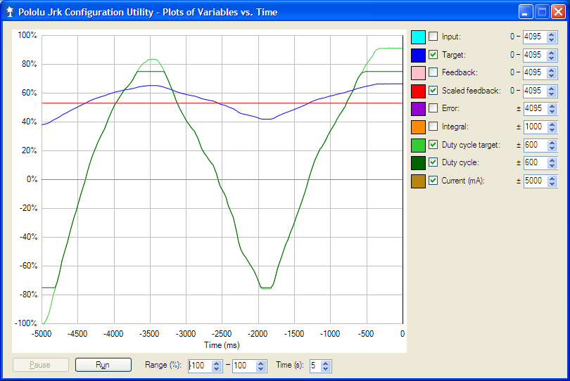
In your video, you mention that the red line doesn’t quite meet the blue line. This might be solvable with an appropriate integral term. Once you have that integral term, you can test your system to see how close the scaled feedback and target can get, and set your feedback deadzone to something a little higher than that. If your deadzone is too large, then the feedback will be far from the target. If it is too low, you’ll see the jrk trying to drive the motor at a low duty cycle when the dome is not moving.