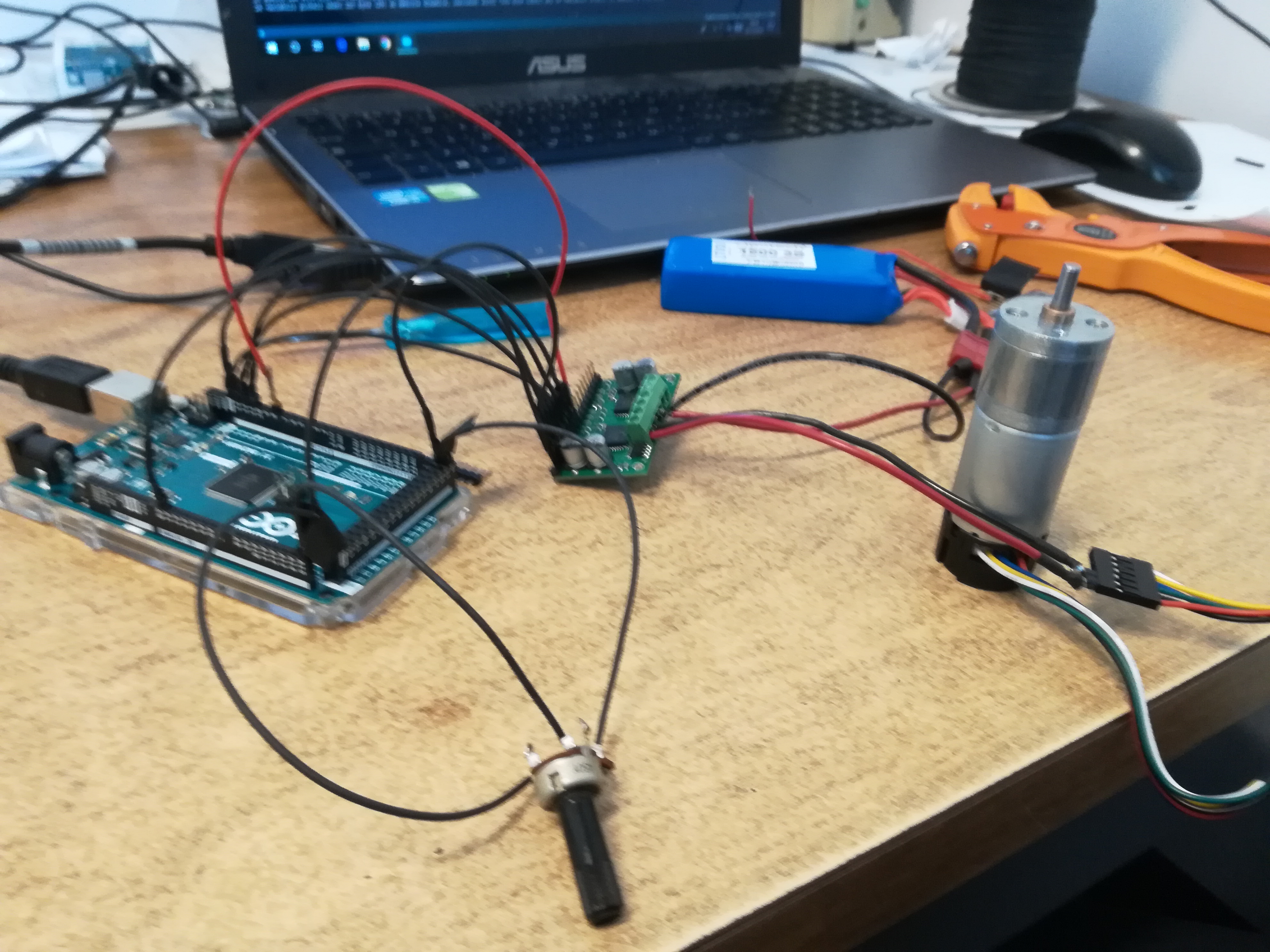
I use a Dual MC33926 Motor Driver Carrier and an Arduino to drive a motor with variable speed and direction. Arduino is supplied by its USB, the driver is powerd by a 3S 1500mAh battery.
This system is able to correctly drive a motor I already have (this), but if I change the motor with a 75:1 Metal Gearmotor 25Dx69L mm HP 12V the system does not work anymore.
Rarely the motor starts and the control works as intended, but if the control stops the motor, the motor does not start anymore.
Measuring the voltage between M1OUT1 and M1OUT2, I get the correct values (between -11.3V and +11.3V) if the old motor is connected or if there is no motor, but when the 75:1 gearmotor is connected the maximum measured voltage is around 2.8V so it does not start.
Can you post some pictures of your setup that show the motor, the driver, and all of your soldered connections?
Could you also try connecting the motor directly to your battery? Does the motor appear to work normally in that simplified setup? What is the battery voltage and current draw in that case?
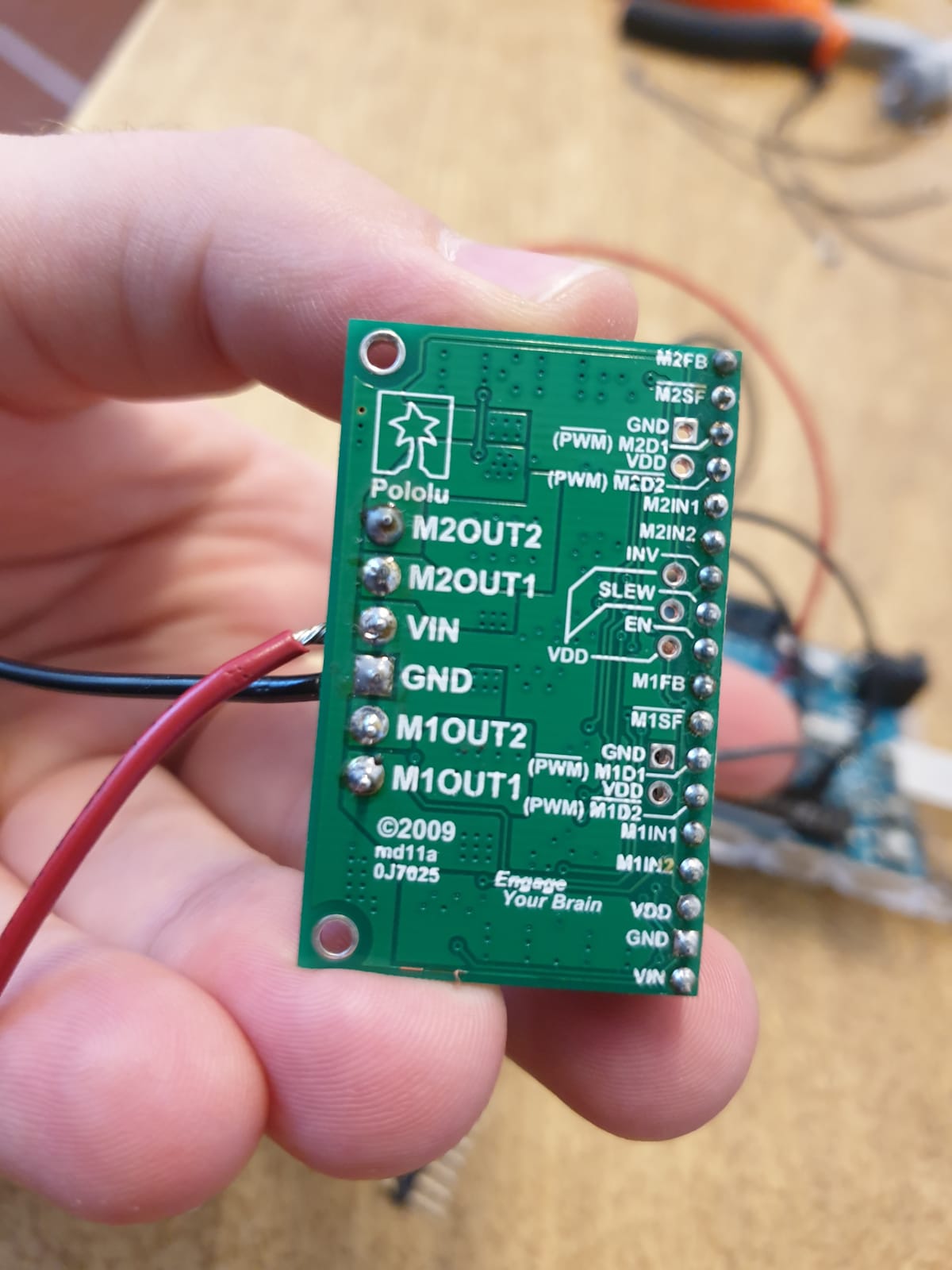
These are the connection with the motor driver:
VIN Battery positive cable
GND Battery negative cable
M1OUT1 motor black cable
M1OUT2 motor red cable
GND GND
VDD 5V from arduino
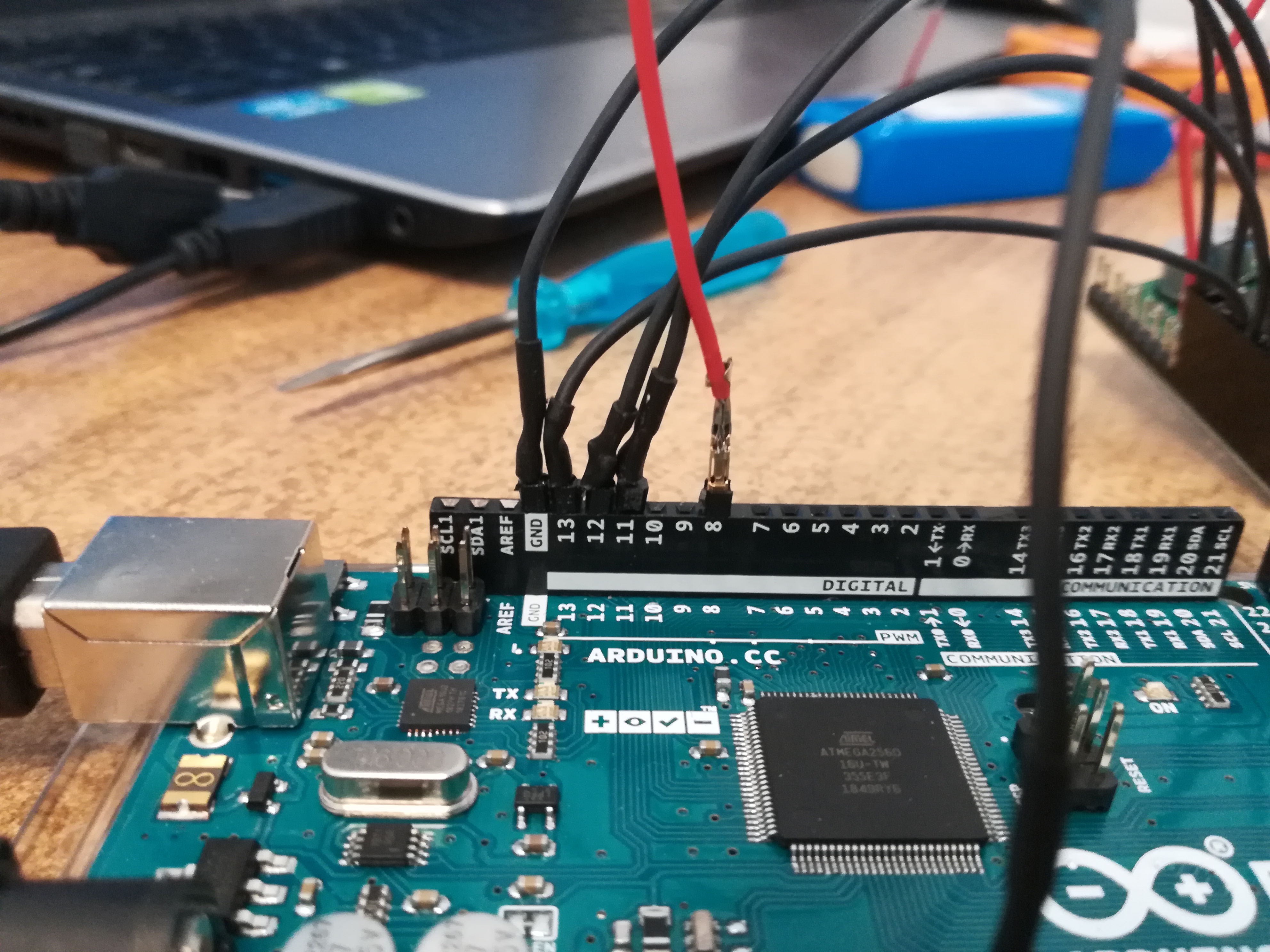
M1IN1 PIN 12
M1IN2 PIN 11
PWMM1D2 GND
PWMM1D2 PIN 13
EN PIN8
I tried to connect the motor directly to the battery and it works. The measured voltage in this case is 11.74V (the battery alone had a voltage of about 11.8V when I start testing) and the measured current is 200mA (a value less then the 300mA from the datasheet).
So I tried againg the setup with the motor driver but the issue with the huge voltage drop still occours.
I tried also another 75:1 Metal Gearmotor 25Dx69L mm HP 12V that I have but it does not work.
I then found in my lab a 50:1 Metal Gearmotor 37Dx70L mm. I tried it with the motor driver and it works as expected modulating its speed and changing direction.
I also tested the driver without any motor and from the motor pin i measure the expected values.
So to summarize I tested 4 motors, the one linked in the first post, 2 different 75:1 Metal Gearmotor 25Dx69L mm HP 12V and one 50:1 Metal Gearmotor 37Dx70L mm. All of them works if directly connected to the battery. If I use the motor driver, instead, the two 75:1 motors don’t works anymore while the other two work as intended.
So I belive the code, the motor driver and the connections are working. The motors work too because they spin if connected to the battery. But when i connect the 75:1 gearmotors to the driver, the voltage drop is so high they can’t spin anymore.
Hello,
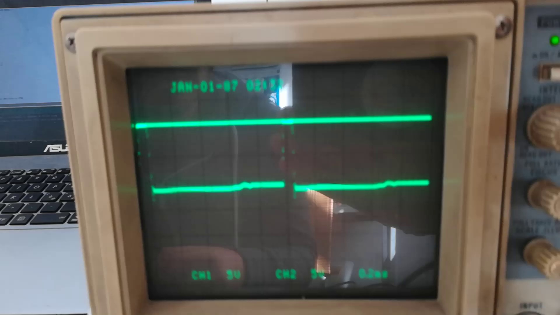
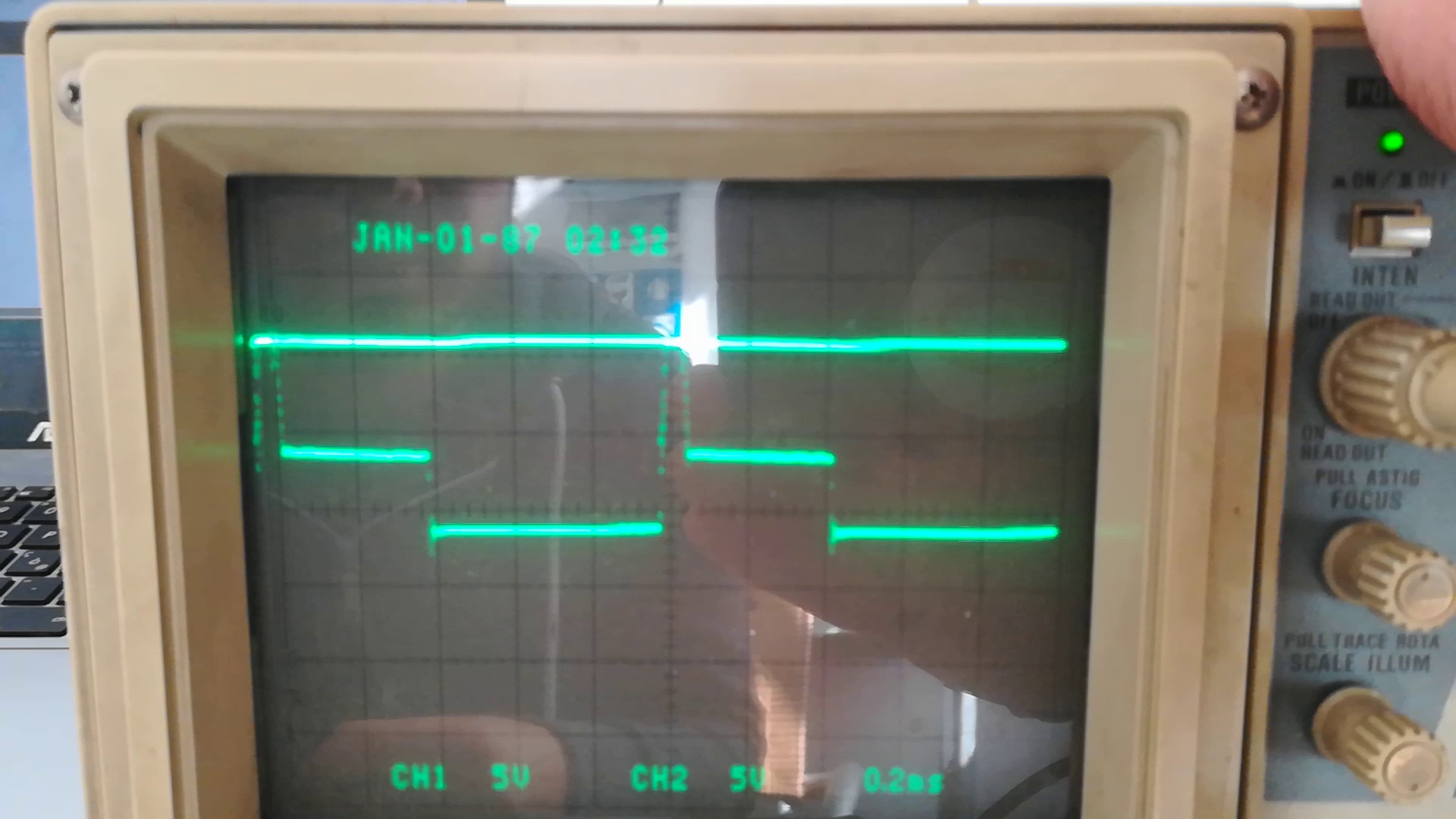
I share with you some of the screen captures. I have to tell you, however, that during this test the motor was able to rotate in one direction and different speeds. But I don’t know why. I also checked with a multimeter the IN1 and IN2 signals, but they were ok.
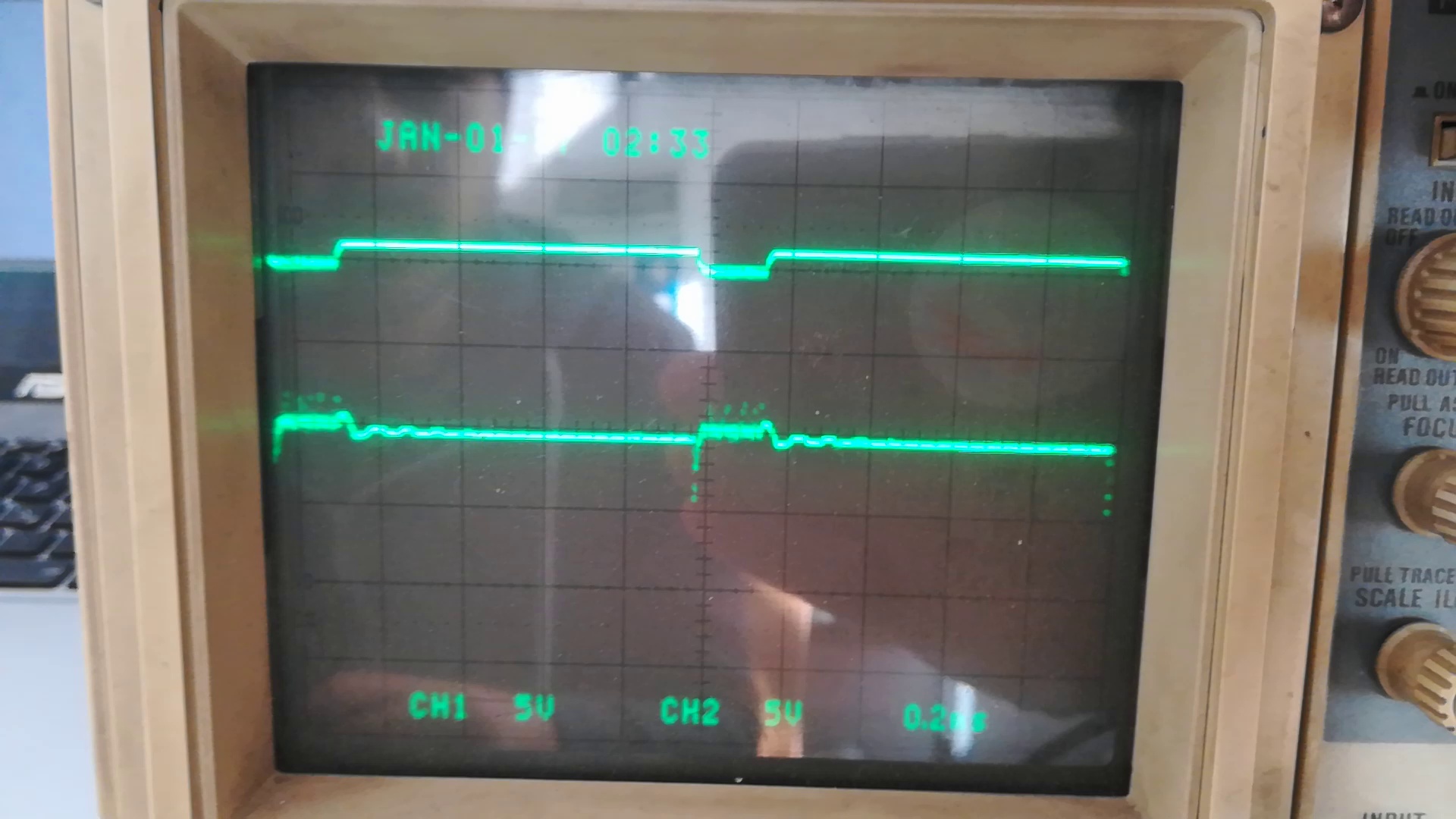
This is the oscilloscope at start, with PWM equal 0 (lower line). The top line is the battery (11.5V)
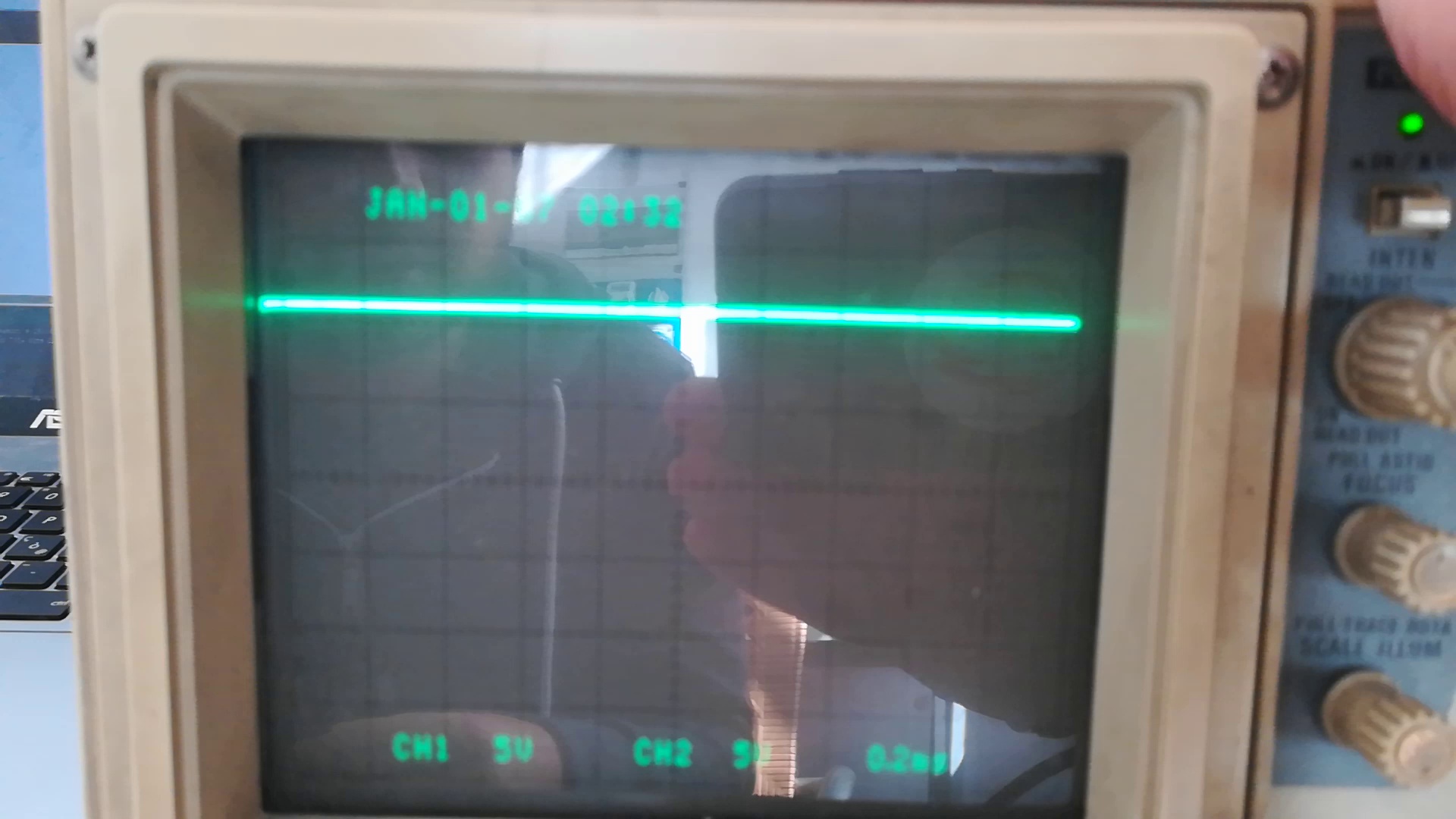
If i reverse the direction instead i get this (values around 1 or 2 Volts like the one i measured with the multimeter when the motor was not spining in any direction):
Sincerely, I don’t know anymore what is happenening.
I can try to make new connections, try the M2 ports or even solder a new driver carrier, if you think it may works.
That motor is overpowered for your driver, so it is probably triggering the driver’s over-current limiting, which is not quite enough to get the motor spinning most of the time. If you need to use this driver, then you could try to work around the high startup current by either giving your motor a kick-start by hand to get it going, or by ramping the PWM signal to reduce the initial current draw on startup. However, you would probably be better off with getting a more appropriately powerful driver, like our VNH5019 carrier, which is also available as dual driver PCB.
Thanks, I checked again the data and you are right, the stall current is 5.6A while the peak current of the driver is 5A.
Since the difference is not so high, do you belive that if I add a very little resistance in series to the motor it could works?
I would suggest trying to ramp the speed first (and possibly limit the maximum duty cycle), but adding a resistor in series with your motor is certainly an option you can try. If you go that route, make sure you use a resistor that is rated to dissipate that kind of power, and note that you will decrease the maximum power the motor can produce. Please let me know if either options do not get things working for you.