I used this thread to get help for interfacing my micro maestro, i have now changed it to help others interface it with mikroC for PICs and a PIC16F84A chip
I recently received my Micro Maestro 6ch servo controller and was messing and experimenting with it and thought of a way of improving the uses of this board. I am not sure whether this would mean updating the firmware or the control software.
In the ‘Pololu Maestro Control Centre’ under the ‘Channel Settings’ tab, where it says ‘Mode’. On this drop down menu you could implement something like ‘Servo Input’ Which allows you to instead of controlling the servos with the pulse, detecting pulses such as from the signal port of an RC receiver. I understand that this may be done via the scripting but i believe this way would make it a lot simpler.
This feature would mean that customers could hereby use the maestro controllers to make custom servo mixers for obscure radio controlled craft.
I know i would use this feature and i am sure many others would aswell. I hope the programmers and development department will take my suggestion on and i believe it would expand the uses of this device.
Peter
EDIT: just reading the other threads, thought i would just add i am using XP pro if that helps.
Hello, and thanks for the suggestion. I do like the idea of being able to do arbitrary mixing with a script, but unfortunately, it is beyond the capabilities of the Maestro, even with a firmware upgrade. Generating each servo pulse occupies the processor for a few tens of microseconds, so it would be really hard to measure incoming pulses with reasonable precision. If you want to do this, your best bet is to use a Baby Orangutan with our pulse-measuring library to measure the pulses, then send serial commands to the Maestro.
Maybe that could be another product all together that ties via serial into a servo controller. I am sure i could work something out for now with a PIC.
Might as well put this in this thread, save making another one, with the scripting, what else can you do? can you do if arguments? liked do something if an input is at a certain position?
That would be a nice product, but maybe example Orangutan code would be a good start? We think there are a lot of things you could do with scripting. The script language is a full-featured programming language that can do anything, though complicated programs will be hard to write. Have you looked over the scripting language reference?
In input mode, a channel just measures the voltage on the line. There are no built-in pull-up resistors, so for simple sensors you need to include your own. Note that you should not apply voltages above 5V or below 0V to the inputs - so the pull-up resistor usually should not be connected to the servo power line.
Here are some ideas for programs:
Highly compressed motion sequences - as an example, you could start a smooth motion with an acceleration limit, and delay until the motion is complete before starting the next one, so just a few bytes are needed to encode something that would normally take many frames.
Sequences that are activated by serial commands from an external microcontroller.
Simple responses to sensors - e.g. a Halloween display triggered by a motion detector.
Very simple robots. The hexapod walker pictured on the Maestro page has room for three sensors and some simple pre-programmed behaviors.
Control a servo with a potentiometer as a simple servo tester.
Might have a go of that hexapod then, maybe my idea could be implemented into a future product.
Dont suppose you know anything about coding PICs, i wrote this code, put it on a PIC then connected it up to my maestro, nothing happened bit confused, may have put it in the wrong format.
Can the inbuilt scripting be used to read TTL information sent?
So i can use a PIC to do the sensing of the receiver output then feeding the raw information intot he maestro then using the scripting to generate the output?
We can’t fully support your PIC coding efforts, but one thing I noticed immediately was that the line above if probably wrong. Are you coding in C? You should review what the + operator does in C. The line above is wrong because it is equivalent to
Soft_UART_Write(0x12E); // wrong
But you don’t want to add the bytes together, you want to send them in series. You probably need to call Soft_UART_Write multiple times.
Yes. There is a serial command called Restart script at subroutine with argument that lets you pass 14 bits of data to the scripting language. This command is documented in the Maestro user’s guide. The PIC can feed information to the Maestro using this command.
That looks like the right sequence for a Pololu protocol command that sets the target of servo 0 to 1.5 ms. Are you planning to connect multiple devices on the same serial line? If not, you should probably use the compact protocol, which is simpler and faster. Just make sure that you send the 0xAA the first time unless you set up a fixed baud rate.
How are you activating the PIC? Do you use the reset line to make sure that the command is not sent right at power-up, before the Maestro has a chance to start up?
Also, I do not know exactly who your environment works, but you should probably put a while(1); or something at the end so that the main() function never has to return, unless you really know what you are doing.
Finally, you can check for errors and results in real time using the Maestro Control Center and let us know what the LEDs on the board are doing before and after you send the signal.
To tell the truth i am having a bit of trouble with the PIC at the moment, i think it might have something to do with the resonator, i cant even get an LED to flash
PORTA pin 1 would probably be RA1. I still do not know what C compiler you are using and where the Soft_UART functions come from, so I cannot really tell you for sure how to make it work.
When you say it is both “working” and “doesn’t seem to be working” do these two comments apply to the same code? Do you mean that the LED flashes, but you get serial errors on the Maestro? Can you tell us what the errors are?
Also, where in your code do you specify the resonator frequency, and what is it? Do have a scope or some other way of testing your PIC’s output? It can be hard to get that right the first time.
Well what i meant was the LED flashes but servo 0 does not move, the green light next to the red light flashes. The compiler is mikroC for PICs, the soft_uart is an accompanying library. The freequency thing is a preference in the program.
Bit confused as to why you need 14 bits of information to send the servo target, why does it have high bits and low bits? and i dont see how you get 112 and 46 from 6000?
If you can tell me about your serial errors, I can help you figure out what is going on. Without knowing the specific errors, which are designed to help you debug problems, there is not much point talking about it! It would also be useful to know how your clock is set up (you said you suspected you were doing it wrong), how you have connected your PIC to your Maestro (can you post a picture?) and whether you have access to an oscilloscope.
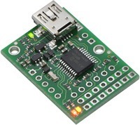
There is a green LED next to the USB connector, and red and yellow LEDs next to each other by the servo outputs. Can you describe exactly what the various LEDs are doing before and after you send the serial command? Something like, “before the command is sent, the green and red LEDs are off and the yellow LED is flashing very briefly about once per second. After the command is sent, the red LED is on and the yellow LED is dimly lit.”
Actually…I notice that you still have no delay before sending the initial command, so if your Maestro and PIC share the same power supply, that might be causing problems.
As for the 14 bits of information - the target is a 14 bit number (from 0 to 16383) that represents a pulse duration in quarter-microseconds (from 0us to 4095.75us, though there are limits on these values depending on your configuration). The manual shows exactly where the numbers 112 and 46 come from, so I am not sure what else to tell you about that. Another thing I could say is that 6000/128 is 46 with a remainder of 112, or 6000 = 46*128+112.
I am almost completely sure the serial link is ok, i only get the error when i swap round the Tx and Rx, otherwise it is just the yellow light on.
I power up the maestro with a 4.8v Rx pack for the servos then i have it hooked up to the USB to power the processor, i then power up the PIC which is running this code:
The yellow LED should never just be “on”. Are you sure it is not blinking somehow? Anyway, if you have swapped TX and RX, you have almost certainly created a short from power to ground at some point and it is possible that you have damaged your Maestro, the PIC, or both - so do not do that again. It is strange that you would say there is an error when they are swapped, since the error can only occur when an improper signal is sent to the Maestro’s RX line. Please post details on how you have connected TX, RX, and GND, and how you power the PIC. Do you have access to an oscilloscope?
I see two more obvious problems with your approach here - first, you set all of your I/O lines to outputs at the beginning of your code, which I believe will cause both a dangerous short to TX and an incorrect low pulse on RX, before you call soft_uart_init(). Second, you are no longer sending the start byte 0xAA, which is required for every command in the Pololu protocol. If you want to not send that byte, you need to switch to the compact protocol.
In general, you need to answer all of my questions and give me details about what is going on if you want me to help you. Saying that you are “almost completely sure” some part is okay is not reasonable when there is obviously a problem somewhere in your system, and you know that you have been confused about that part!
Yes, i meant the yellow light was flashing at about 1hz. The Tx (Maestro) is connected to RA1 on the PIC and Rx (Maestro) to RA2. GND is just connected to Vss on the PIC. Should i try setting the pin connected to the maestro Tx to an input?
No i don’t have an oscilloscope.
I also tried doing the compact protocol with no success.