
Hi all!
I am using wixel first time and new to i2c, serial connections, etc. so please sorry for dumb questions 
I installed i2c app to wixel and tried to see if my i2c device (minimu 9 v5) is sending something to it.
Of course, there was nothing, because it needed command to read some value. I tried typing simple E to read errors but it just does not respond. I can type and pressing enter does nothing.
It seems like I am basically doing something very trivial wrong. Please help me to read a value from my IMU with wixel
The IMU is a rather complicated device and requires a number of commands to initialize it and then read out data. Unless there is a code library for the Wixel and the MinIMU-9 V5, the easiest way to start is to use an Arduino compatible microcontroller and the Pololu Arduino library for the IMU.
Follow the instructions in the MinIMU-9 V5 product page, starting at Sample Code.
Thanks for your reply!
I already worked with that IMU. Previously I used beaglebone and arduino to read data from that IMU but now I need it to be wireless. Also, it is a bit redundant to use microcomputer like beaglebone/raspberry or any arduino only to read data using i2c connection. I already know how to read data using i2c, but here with wixel it works differently.
For example, as far as I remember, it is possible to connect to beaglebone using putty and command through it to read values from or to write value into the device via i2c. According to wixel user guide the only thing required is to send character ‘E’ to the wixel (serial write) while being connected via usb.
However, I cannot write any data to wixel using putty. Again, sorry for these stupid questions, but I need to read IMU data only using wixel without any additional microcontrollers 
It will be no problem to read that IMU using the Wixel. You just have to write the code!
Hello, hayemon.
Like Jim_Remington mentioned, the sensors on the MinIMU-9 require a number of commands to initialize them and read their data. The Wixel Serial-to-I²C app has no knowledge of those MinIMU-9 commands, so you will have to put together your own sequences of bytes to send to the Wixel running the Serial-to-I²C app. To begin that, I recommend reviewing the example sequences inside the Serial-to-I²C section of the Wixel’s user’s guide and then try to send the I²C commands that we use in our MinIMU Arduino library.
Also, for clarification: the ASCII character ‘E’ is recognized as a command to get errors when using the Wixel Serial-to-I²C app. So, it cannot be used to send a meaningful stream of bytes to initialize and read data from the MinIMU.
-Jon
Hi, Jonathan.
Thank you for your reply. I have written c# code in unity and it responds with 0 value. I am trying to read value from 0x22 register of lsm6ds33 which is inside of minimu9 v-5.
Here is my code:
using System.Collections;
using System.Collections.Generic;
using UnityEngine;
using System.IO;
using System.IO.Ports;
using System.Threading;
using System;

public class reader : MonoBehaviour {

	#region public variables
	#endregion
	#region private variables
	private SerialPort port1;
	private string port1_name;
	private byte gyro_acc_address_lsb_0;
	private byte gyro_acc_address_lsb_1;
	private byte out_gyro_address_l;
	private byte out_gyro_address_h;
	#endregion

	public reader (){
		string header_to_file = @"\\.\";
		port1_name=header_to_file+"COM20";
		port1 = new SerialPort(port1_name, 9600, Parity.None, 8, StopBits.One); // port settings
		port1.ReadTimeout = 5;
		port1.Handshake = Handshake.None;
		port1.Open();
		port1.DiscardOutBuffer();
		port1.DiscardInBuffer();
		gyro_acc_address_lsb_0 = 0x6A;
		gyro_acc_address_lsb_1 = 0x6B;
		out_gyro_address_l = 0x22;
	}

	public string readSerial(){
		string text = null;
		try {
			port1.Write ("S");
			port1.Write (new byte[]{ gyro_acc_address_lsb_0 }, 0, 1);
			port1.Write ("1");
			port1.Write (new byte[]{ out_gyro_address_l }, 0, 1);
			port1.Write ("S");
			port1.Write (new byte[]{ gyro_acc_address_lsb_1 }, 0, 1);
			port1.Write ("2");
			port1.Write ("P");
			int response = port1.ReadByte ();
			text = response.ToString ();
			Debug.Log (response);
			Debug.Log ("lolka");

		} catch (TimeoutException) {
			Debug.Log ("Timeout");
		}
		return text;
	}
}
another file which runs previous one:
using System.Collections;
using System.Collections.Generic;
using UnityEngine;

public class controller : MonoBehaviour {

	#region variables
	public reader valReader;
	private string text;
	#endregion
	// Use this for initialization
	void Start () {
		valReader = new reader ();
	}

	// Update is called once per frame
	void Update () {
		text = valReader.readSerial();
	}
}
It looks like you are not enabling or configuring the LSM6. You need to enable and configure the LSM6 before reading any data registers. I recommend reading through the enableDefault() function of the LSM6 library.
-Jon
I have added control lines as you proposed. Also, I found out that I connected IMU to wixel not properly. Now it sends me 255 from both registers (low and high)
So, SDA and SCL of imu should be connected to SDA and SCL pins on wixel initialized via serial to i2c app; ground to ground and Vin to 3v3 output voltage of the wixel. right?
Also, red LED on wixel turns on and green LED starts blinking when I run my code.
using System.Collections;
using System.Collections.Generic;
using UnityEngine;
using System.IO;
using System.IO.Ports;
using System.Threading;
using System;

public class reader : MonoBehaviour {

	#region public variables
	#endregion
	#region private variables
	private SerialPort port1;
	private string port1_name;
	private byte gyro_acc_address_lsb_0;
	private byte gyro_acc_address_lsb_1;
	private byte out_gyro_address_l;
	private byte out_gyro_address_h;
	private byte ctrl1_xl;
	private byte ctrl2_g;
	private byte ctrl3_c;
	#endregion

	public reader (){
		string header_to_file = @"\\.\";
		port1_name=header_to_file+"COM20";
		port1 = new SerialPort(port1_name, 9600, Parity.None, 8, StopBits.One); // port settings
		port1.ReadTimeout = 5;
		port1.Handshake = Handshake.None;
		port1.Open();
		port1.DiscardOutBuffer();
		port1.DiscardInBuffer();
		gyro_acc_address_lsb_0 = 0x6A;
		gyro_acc_address_lsb_1 = 0x6B;
		out_gyro_address_l = 0x22;
		out_gyro_address_h = 0x23;
		ctrl1_xl = 0x10;
		ctrl2_g = 0x11;
		ctrl3_c = 0x12;

		i2cWrite (port1, gyro_acc_address_lsb_0, ctrl1_xl, 0x80);
		i2cWrite (port1, gyro_acc_address_lsb_0, ctrl2_g, 0x80);
		i2cWrite (port1, gyro_acc_address_lsb_0, ctrl3_c, 0x04);
	}

	public string readSerial(){
		string text = null;
		try {
			int response1 = i2cRead(port1, gyro_acc_address_lsb_0, out_gyro_address_l, gyro_acc_address_lsb_1);
			int response2 = i2cRead(port1, gyro_acc_address_lsb_0, out_gyro_address_h, gyro_acc_address_lsb_1);
			text = response1.ToString ()+" "+response2.ToString();
			Debug.Log (text);

		} catch (TimeoutException) {
			Debug.Log ("Timeout");
		}
		return text;
	}

	private void i2cWrite(SerialPort port, byte deviceAddress, byte regAddress, byte ctrlWord){
		port.Write("S");
		port.Write (new byte[]{ deviceAddress }, 0, 1);
		port.Write("2");
		port.Write (new byte[]{ regAddress }, 0, 1);
		port.Write(new byte[]{ctrlWord}, 0 ,1);
		port.Write("P");
	}

	private int i2cRead(SerialPort port, byte deviceAddress_l, byte regAddress, byte deviceAddress_h){
		port.Write ("S");
		port.Write (new byte[]{ deviceAddress_l }, 0, 1);
		port.Write ("1");
		port.Write (new byte[]{ regAddress }, 0, 1);
		port.Write ("S");
		port.Write (new byte[]{ deviceAddress_h }, 0, 1);
		port.Write ("2");
		port.Write ("P");
		return port1.ReadByte ();
	}
}
Power connected at VIN on the MinIMU is connected to an on-board 3.3V regulator. So, although it is okay to supply 3.3V power to VIN on the MinIMU, it would be more energy efficient to just bypass the 3.3V regulator and connect 3.3V from the Wixel to the VDD pin on the MinIMU. You can read more about the differences between VIN and VDD in the table under the Pinout section of the MinIMU’s product page.
The behavior of the indicator LEDs can change based on which App is loaded on the Wixel, and their behavior is described in the appropriate section of the Wixel’s user’s guide (i.e. look for a description of the LED behavior on your Wixel loaded with the Serial-to-I²C App in the Serial-to-I²C App section of the user’s guide). For the Serial-to-I²C App, the green LED also flickers when there is data transferred over USB, which looks like what you could be noticing. The red LED indicates that there are errors. Can you use the Get Errors command (‘E’) to get the error byte and share what that byte is here?
-Jon
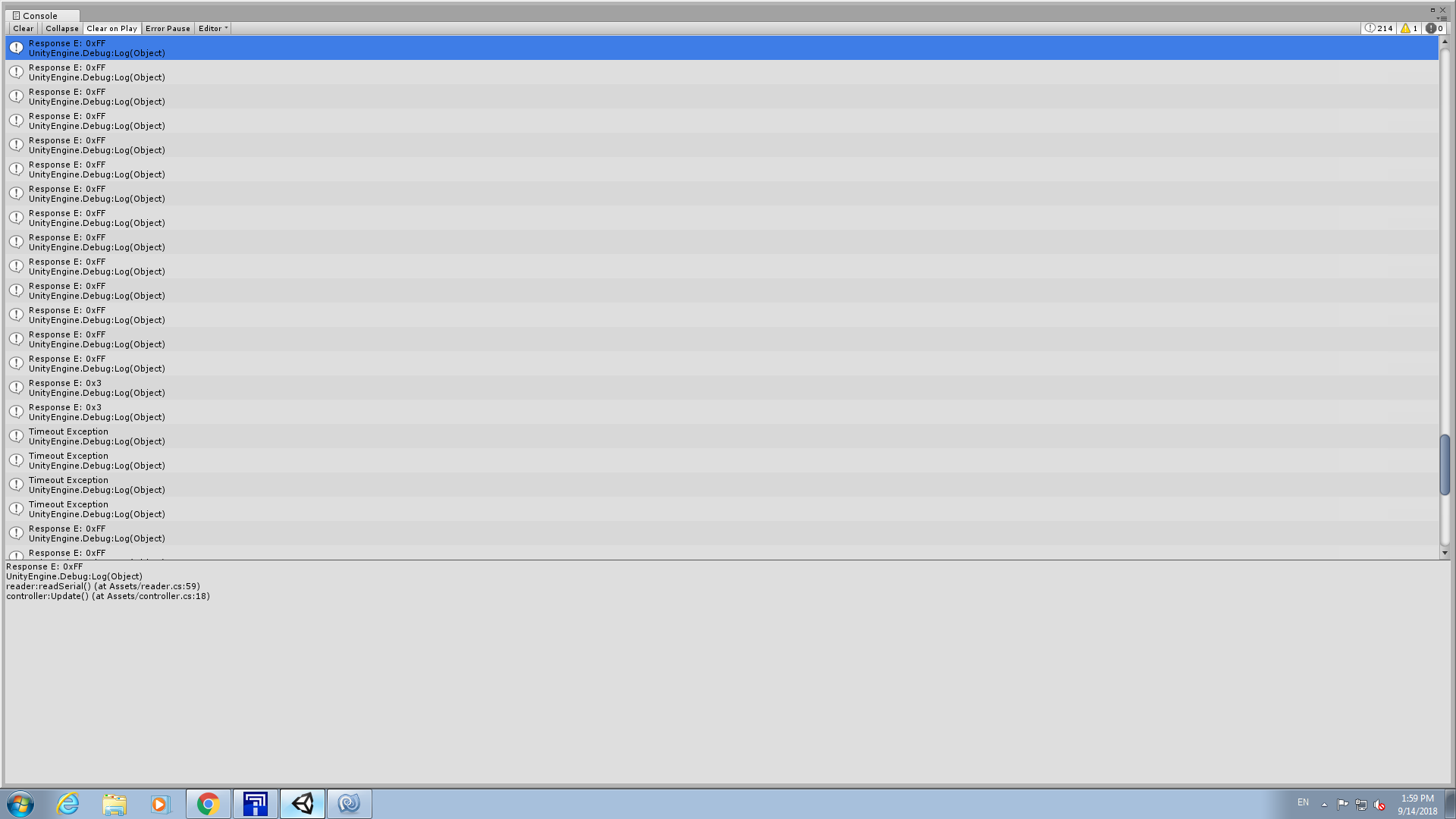
Again thank you for your help! I added error request line. When I run only it without writing anything to the device, I got 0x0 and red LED is off. When I start reading one of the registers red LED turns on and I got 0xff from after requesting error code. Also, sometimes 0x3 value appears. The screenshot is attached as well as the code.
According to that error code it seems like I am sending improper values to the device to read required values. Also, taking into account the fact that when I request only error I also write commands to ctrl registers of the IMU, and red LED does not turn on, my i2cWrite is working properly (I suppose). Cannot understand why i2cRead is not working ![]()
using System.Collections;
using System.Collections.Generic;
using UnityEngine;
using System.IO;
using System.IO.Ports;
using System.Threading;
using System;

public class reader : MonoBehaviour {

	#region public variables
	#endregion
	#region private variables
	private SerialPort port1;
	private string port1_name;
	private byte gyro_acc_address_lsb_0;
	private byte gyro_acc_address_lsb_1;
	private byte out_gyro_address_l;
	private byte out_gyro_address_h;
	private byte ctrl1_xl;
	private byte ctrl2_g;
	private byte ctrl3_c;
	#endregion

	public reader (){
		string header_to_file = @"\\.\";
		port1_name=header_to_file+"COM20";
		port1 = new SerialPort(port1_name, 9600, Parity.None, 8, StopBits.One); // port settings
		port1.ReadTimeout = 5;
		port1.Handshake = Handshake.None;
		port1.Open();
		port1.DiscardOutBuffer();
		port1.DiscardInBuffer();
		gyro_acc_address_lsb_0 = 0x6A;
		gyro_acc_address_lsb_1 = 0x6B;
		out_gyro_address_l = 0x22;
		out_gyro_address_h = 0x23;
		ctrl1_xl = 0x10;
		ctrl2_g = 0x11;
		ctrl3_c = 0x12;

		i2cWrite (port1, gyro_acc_address_lsb_0, ctrl1_xl, 0x80);
		i2cWrite (port1, gyro_acc_address_lsb_0, ctrl2_g, 0x80);
		i2cWrite (port1, gyro_acc_address_lsb_0, ctrl3_c, 0x04);
	}

	public string readSerial(){
		string text1 = null;
		string text2 = null;
		try {
			byte response1 = i2cRead(port1, gyro_acc_address_lsb_0, out_gyro_address_l, gyro_acc_address_lsb_1);
			//byte response2 = i2cRead(port1, gyro_acc_address_lsb_0, out_gyro_address_h, gyro_acc_address_lsb_1);
			byte responseToError = i2cReadError(port1);

			//text1 = response1.ToString ()+" "+response2.ToString();
			text2 = responseToError.ToString();
			//Debug.Log("Response 1: 0x"+String.Format("{0:X}", response1));
			//Debug.Log("Response 2: 0x"+String.Format("{0:X}", response2));
			Debug.Log("Response E: 0x"+String.Format("{0:X}", responseToError));

		} catch (TimeoutException) {
			Debug.Log ("Timeout Exception");
		}
		return text1+", "+text2;
	}

	private void i2cWrite(SerialPort port, byte deviceAddress, byte regAddress, byte ctrlWord){
		port.Write("S");
		port.Write (new byte[]{ deviceAddress }, 0, 1);
		port.Write("2");
		port.Write (new byte[]{ regAddress }, 0, 1);
		port.Write(new byte[]{ctrlWord}, 0 ,1);
		port.Write("P");
	}

	private byte i2cRead(SerialPort port, byte deviceAddress_l, byte regAddress, byte deviceAddress_h){
		port.Write ("S");
		port.Write (new byte[]{ deviceAddress_l }, 0, 1);
		port.Write ("1");
		port.Write (new byte[]{ regAddress }, 0, 1);
		port.Write ("S");
		port.Write (new byte[]{ deviceAddress_h }, 0, 1);
		port.Write ("2");
		port.Write ("P");
		return (byte)port.ReadByte();
	}

	private byte i2cReadError(SerialPort port){
		port.Write ("E");
		return (byte)port.ReadByte();
	}
}
It looks like you are using the wrong slave addresses. In particular, it looks like you are mixing up the least-significant bit of the 7-bit slave address (SA0) and the I²C direction bit, which is an additional 8th bit.
To clarify the structure of the LSM6DS33’s slave address: the device slave address of the LSM6 will always begin with the 6 bits 110101. Then, the next bit in the address depends on the state of the SA0 pin. If it is high, like it is by default on our boards, the value of that bit is 1. If the SA0 pin is driven low, then the value of that bit is 0. Finally, the 8-bit slave address’s LSB (the I²C direction bit) should be 0 for write and 1 for read. So if SA0 is high, the write address for the purpose of the Wixel Serial-to-I²C App should be 0b11010110 or 0xD6, and the read address should be 0b11010111 or 0xD7. Alternatively, if you have driven SA0 low, the write address should be 0b11010100 or 0xD4, and the read address should be 0b11010101 or 0xD5.
If you are wondering why the slave addresses are defined differently in our Arduino library, the reason is that Arduino’s Wire library automatically adds the last bit depending on the direction (write or read), so the library only defines a 7-bit address for when SA0 is high (0b1101011) and another for when SA0 is low (0b1101010).
Also, another issue you might run into is writing string values like “2” (i.e. the character ‘2’) instead of the value 2. For example, instead of port.Write("2");, it should probably be something like port.Write (new byte[]{ 2 }, 0, 1);
Additionally, it might be easier to combine all of your writes into a single buffer:
port.Write (new byte[]{ 'S', deviceAddress, 2, regAddress, ctrlWord, 'P' }, 0, 6);
-Jon
Thank you very much! Seems like the problem was in device address. However, the is another problem now ![]()
On IMU I connected only SCL, SDA, GND and VDD and did not touch SA0 pin. However, when I used 0xD4 and 0xD5 addresses it responded with 0xFF again (the same as before).
When I changed addresses to 0xD6 and 0xD7 it showed me the following:
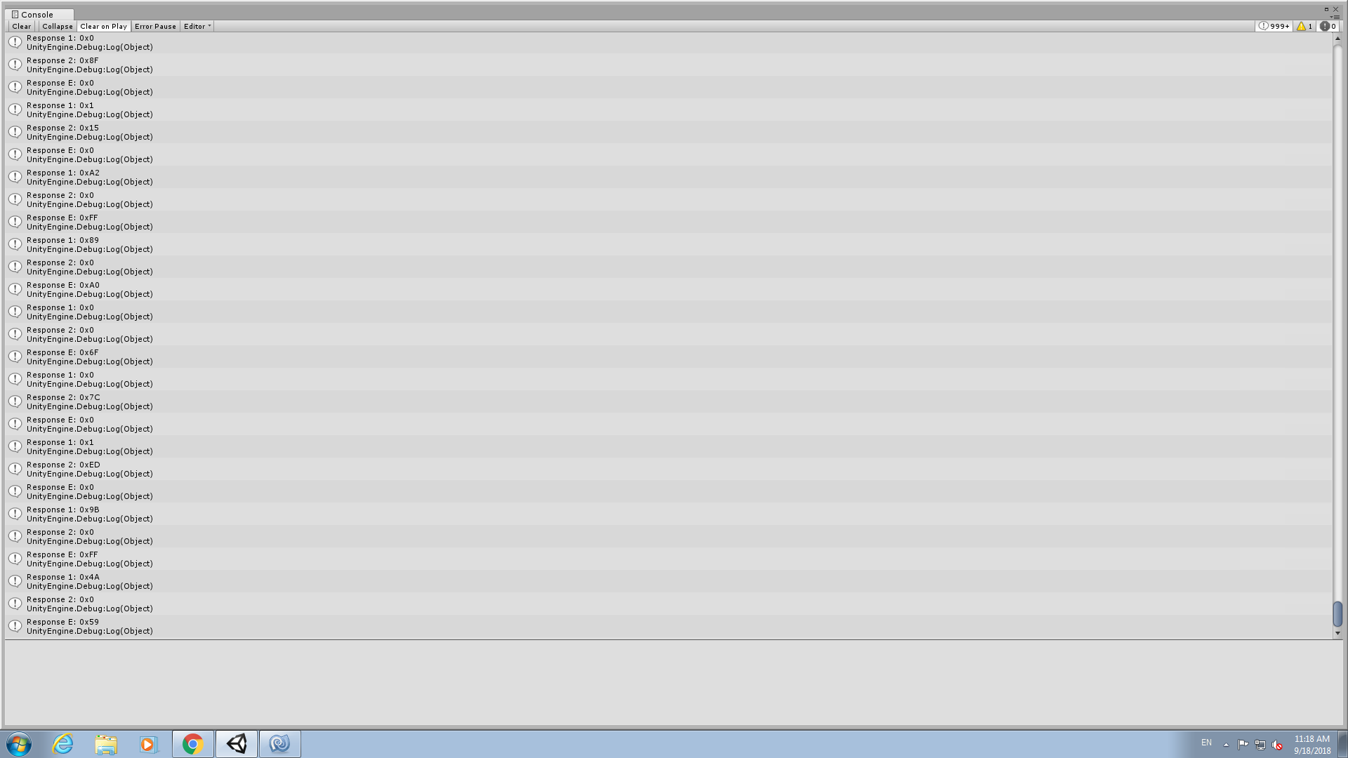
Even though it responds to error request with some weird values, red LED does not turn on. So seems like there is no error but response shows that there is ![]()
Also, I did not clearly understand what those 1 and 2 values in read and write functions mean? Are they some sort of identifiers or number of bytes to write/read?
Current code is here:
using System.Collections;
using System.Collections.Generic;
using UnityEngine;
using System.IO;
using System.IO.Ports;
using System.Threading;
using System;

public class reader : MonoBehaviour {

	#region public variables
	#endregion
	#region private variables
	private SerialPort port1;
	private string port1_name;
	private byte gyro_acc_address_lsb_0;
	private byte gyro_acc_address_lsb_1;
	private byte out_gyro_address_l;
	private byte out_gyro_address_h;
	private byte ctrl1_xl;
	private byte ctrl2_g;
	private byte ctrl3_c;
	#endregion

	public reader (){
		string header_to_file = @"\\.\";
		port1_name=header_to_file+"COM20";
		port1 = new SerialPort(port1_name, 9600, Parity.None, 8, StopBits.One); // port settings
		port1.ReadTimeout = 5;
		port1.Handshake = Handshake.None;
		port1.Open();
		port1.DiscardOutBuffer();
		port1.DiscardInBuffer();
		//gyro_acc_address_lsb_0 = 0x6A;
		//gyro_acc_address_lsb_1 = 0x6B;
		gyro_acc_address_lsb_0 = 0xD6;
		gyro_acc_address_lsb_1 = 0xD7;
		out_gyro_address_l = 0x22;
		out_gyro_address_h = 0x23;
		ctrl1_xl = 0x10;
		ctrl2_g = 0x11;
		ctrl3_c = 0x12;

		i2cWrite (port1, gyro_acc_address_lsb_0, ctrl1_xl, 0x80);
		i2cWrite (port1, gyro_acc_address_lsb_0, ctrl2_g, 0x80);
		i2cWrite (port1, gyro_acc_address_lsb_0, ctrl3_c, 0x04);
	}

	public string readSerial(){
		string text1 = null;
		string text2 = null;
		try {
			byte response1 = i2cRead(port1, gyro_acc_address_lsb_0, out_gyro_address_l, gyro_acc_address_lsb_1);
			byte response2 = i2cRead(port1, gyro_acc_address_lsb_0, out_gyro_address_h, gyro_acc_address_lsb_1);
			byte responseToError = i2cReadError(port1);

			text1 = response1.ToString ()+" "+response2.ToString();
			text2 = responseToError.ToString();
			Debug.Log("Response 1: 0x"+String.Format("{0:X}", response1));
			Debug.Log("Response 2: 0x"+String.Format("{0:X}", response2));
			Debug.Log("Response E: 0x"+String.Format("{0:X}", responseToError));

		} catch (TimeoutException) {
			Debug.Log ("Timeout Exception");
		}
		return text1+", "+text2;
	}

	private void i2cWrite(SerialPort port, byte deviceAddress, byte regAddress, byte ctrlWord){
		port.Write (new byte[]{ Convert.ToByte('S'), deviceAddress, 2, regAddress, ctrlWord, Convert.ToByte('P') }, 0, 6);
		/*port.Write("S");
		port.Write (new byte[]{ deviceAddress }, 0, 1);
		port.Write("2");
		port.Write (new byte[]{ regAddress }, 0, 1);
		port.Write(new byte[]{ctrlWord}, 0 ,1);
		port.Write("P");*/
	}

	private byte i2cRead(SerialPort port, byte deviceAddress_l, byte regAddress, byte deviceAddress_h){
		port.Write (new byte[]{ Convert.ToByte('S'), deviceAddress_l, 1, regAddress, Convert.ToByte('S'), deviceAddress_h, 2, Convert.ToByte('P') }, 0, 8);
		/*port.Write ("S");
		port.Write (new byte[]{ deviceAddress_l }, 0, 1);
		port.Write ("1");
		port.Write (new byte[]{ regAddress }, 0, 1);
		port.Write ("S");
		port.Write (new byte[]{ deviceAddress_h }, 0, 1);
		port.Write ("2");
		port.Write ("P");*/
		return (byte)port.ReadByte();
	}

	private byte i2cReadError(SerialPort port){
		port.Write (new byte[]{Convert.ToByte('E')},0,1);
		return (byte)port.ReadByte();
	}
}
If you leave SA0 untouched, you should use 0xD6 and 0xD7 for the write and read addresses. If the red error LED is not lit, then there are no errors on the Wixel, and running the Get errors command (‘E’) should return 0x00.
Since you are getting seemingly random bytes when running the Get errors command, it seems somewhat likely that your program is actually reading a second data byte when it is expecting an error byte. This might be because you are making a request to read 2 bytes and only reading 1. So, you should either actually read 2 bytes (and combine them and return a short) or change your function to only request 1 byte.
As for your last question, the 1 and 2 values are the number of data bytes to be written or read through the Serial-to-I²C App’s serial commands. This is explained under the Serial-to-I²C section of the Wixel’s user’s guide.
-Jon
Thank you very much for your help!
Now everything works perfectly!
1 Like
Hi Jonathan! I am sorry for asking for another stupid question again
I tried to connect TCA9548A by Adafruit: https://cdn-learn.adafruit.com/downloads/pdf/adafruit-tca9548a-1-to-8-i2c-multiplexer-breakout.pdf
I tried to use the same format as for minimu:
port1.Write (new byte[]{ Convert.ToByte('S'), mux, 1, 0, Convert.ToByte('P')}, 0, 5);
mux is 0x70 as reported in the datasheet. right after that I receive an error:
3 Invalid Command An invalid command byte was received on the serial interface.
described in Wixel serial to i2c app page.
What might be the problem with sending the data?
The overall code:
using System.Collections;
using System.Collections.Generic;
using UnityEngine;
using System.IO;
using System.IO.Ports;
using System.Threading;
using System;

public class reader : MonoBehaviour {

	#region public variables
	#endregion
	#region private variables
	private SerialPort port1;
	private string port1_name;
	private byte gyro_acc_address_lsb_0;
	private byte gyro_acc_address_lsb_1;
	private byte out_gyro_address_l;
	private byte out_gyro_address_h;
	private byte ctrl1_xl;
	private byte ctrl2_g;
	private byte ctrl3_c;
	private byte mux;
	#endregion

	public reader (){
		string header_to_file = @"\\.\";
		port1_name=header_to_file+"COM20";
		port1 = new SerialPort(port1_name, 9600, Parity.None, 8, StopBits.One); // port settings
		port1.ReadTimeout = 5;
		port1.Handshake = Handshake.None;
		port1.Open();
		port1.DiscardOutBuffer();
		port1.DiscardInBuffer();
		//gyro_acc_address_lsb_0 = 0x6A;
		//gyro_acc_address_lsb_1 = 0x6B;
		gyro_acc_address_lsb_0 = 0xD6;
		gyro_acc_address_lsb_1 = 0xD7;
		out_gyro_address_l = 0x22;
		out_gyro_address_h = 0x23;
		ctrl1_xl = 0x10;
		ctrl2_g = 0x11;
		ctrl3_c = 0x12;
		mux = 0x70;

		port1.Write (new byte[]{ Convert.ToByte('S'), mux, 1, 0, Convert.ToByte('P')}, 0, 5);
		int responseToError = i2cReadError(port1);
		Debug.Log (responseToError);
		i2cWrite (port1, gyro_acc_address_lsb_0, ctrl1_xl, 0x80);
		responseToError = i2cReadError(port1);
		Debug.Log (responseToError);
		i2cWrite (port1, gyro_acc_address_lsb_0, ctrl2_g, 0x80);
		i2cWrite (port1, gyro_acc_address_lsb_0, ctrl3_c, 0x04);
	}

	public string readSerial(){
		string text = null;
		try {
			int response1 = i2cRead(port1, gyro_acc_address_lsb_0, out_gyro_address_l, gyro_acc_address_lsb_1);
			int response2 = i2cRead(port1, gyro_acc_address_lsb_0, out_gyro_address_h, gyro_acc_address_lsb_1);
			int responseToError = i2cReadError(port1);

			/*Debug.Log("Response 1: 0x"+String.Format("{0:X}", response1));
			Debug.Log("Response 2: 0x"+String.Format("{0:X}", response2));
			Debug.Log("Response E: 0x"+String.Format("{0:X}", responseToError));*/

			int response=(short)((response2<<8)|response1);
			//Debug.Log(response);

		} catch (TimeoutException) {
			Debug.Log ("Timeout Exception");
		}
		return text;
	}

	private void i2cWrite(SerialPort port, byte deviceAddress, byte regAddress, byte ctrlWord){
		port.Write (new byte[]{ Convert.ToByte('S'), deviceAddress, 2, regAddress, ctrlWord, Convert.ToByte('P') }, 0, 6);
	}

	private int i2cRead(SerialPort port, byte deviceAddress_l, byte regAddress, byte deviceAddress_h){
		port.Write (new byte[]{ Convert.ToByte('S'), deviceAddress_l, 1, regAddress, Convert.ToByte('S'), deviceAddress_h, 1, Convert.ToByte('P') }, 0, 8);
		return (byte)port.ReadByte();
	}

	private int i2cReadError(SerialPort port){
		port.Write (new byte[]{Convert.ToByte('E')},0,1);
		return (byte)port.ReadByte();
	}
}
It looks like you are using the wrong I²C address again. 0x70 (0b1110000) is the 7-bit slave address of the mux you are using, so to write to that address, you should be adding the I²C direction bit (the 8th bit). This bit is zero for write, which means the byte you should send should be 0xE0 (0b11100000).
I would be surprised if you are getting an Invalid Command error. Do you mean that you are getting an error byte value of 3? Note that the table in the user’s guide describes the bits of the error byte, so if you are getting a value of 3 (which is 0b00000011 in binary), that actually means bits 0 and 1 are set, corresponding to the errors I²C NACK on Address and I²C NACK on Data; that is more what I would expect to see if you are sending the wrong address.
-Jon
Oh, I just was too stupid to realize that error is sent not in numbers 0-6 but corresponding bits are set 0 if there is and error… Sorry
Also, with 0xE0 mux receives the first message (0x00) correctly, but aftwerwards minimu connected to 0 channel of mux does not respond to my commands.
It says there are nack in address and data after I use
i2cWrite (port1, gyro_acc_address_lsb_0, ctrl1_xl, 0x80);
		responseToError = i2cReadError(port1);
		Debug.Log (responseToError);
		i2cWrite (port1, gyro_acc_address_lsb_0, ctrl2_g, 0x80);
		responseToError = i2cReadError(port1);
		Debug.Log (responseToError);
As far as I understand, after writing 0 to the mux, it should simply switch to 0 channel i2c devices, so I cannot even guess why it does not respond to these commands
without mux everything works perfectly. Again I am sorry for being so bad with all these things 
I just noticed that it looks like you are using the mux incorrectly. The command byte appears to be a bit field with bit 0 controlling channel 0, bit 1 controlling channel 1, etc. So to enable channel 0 you need to send a byte with bit 1 set (i.e. 0b00000001 or 0x01). Sending 0x00 disables all of the channels.
-Jon
Oh my God…
Please sorry. It really was just like that. I thought it also is simply controlled using some integer value because of aduino sample code of that mux. I understand that I am very annowing I hope later I will not need any help from you, thanks!
1 Like