A gyro alone is useless for this application, because it measures the rate of rotation, not angles. An accelerometer can be used to measure tilt angles, as the acceleration due to gravity defines “down”. That won’t work well if the accelerometer is in motion, so in addition, gyros are used to correct for motion induced errors.
You should work to understand these concepts completely, and implement a simple tiltmeter, before doing anything else in the project. Alternatively, consider using an absolute orientation sensor, like the BNO055, which combines an accelerometer, a gyro and a magnetometer.
hello Jim. Thank you for the information as it is greatly appreciated. However, let me back up a little bit (as I was a little vague in my description of what I was trying to accomplish). I know that the gyro does not measure angles, and, subsequently, needs a accelerometer in order to do so. I am utilizing the mpu6050 (which is an accelerometer / gyro / temp sensor) and I written a sketch that post out all six axis in any way shape and form you can possibly imagine. Angles included. So I know what my XYZ angles are, and I just need to know how to process and digest them in order to maintain this parallelism. I guess the best way to describe it would be a gimbal single-axis along the x axis. That being said, do you have any suggestions? Maybe I can use a PID in conjunction with the MPU6050 data that’s being posted out? I’m just trying to figure out what that code looks like. I just downloaded the PID library so maybe I’ll be able to find something in there that will help. I’m all ears
If you can reliably measure the two tilt angles roll and pitch, then in principle you need two PID loops to correct them.
You probably don’t need the PID library to start understanding the basic principles. If both roll and pitch are defined as zero when the platform is perfectly level, then the simplest correction is just the proportional term of the full PID calculation:
servo_angle = Kp*tilt_angle; //for each of roll and pitch
Adjust Kp (and its sign) by experiment. If the platform oscillates, add in the other K terms or use the full PID library. Google “PID tuning” for advice on choosing the K constants.
Hello Mr. Remington. The roll is a constant measurement as it is mechanically secured in that axis and cannot deviate from it’s orientation. The only axis (I think) that I should be calculating is the x axis and maintaining that parallelism with the Earth. Question: the term “tilt angle” in your code-qgerw does that come from?
And one other question. How do you code or define a continuously rotating servo speed versus a 180° servo?
Also it might be worth nothing that the servos are continuously rotating servos, and I don’t believe that they can accept angle input data. How does this change the aforementioned code that you provided?
You have not described the electromechanical part of your project.
Without that and without a clear explanation for how the servo mechanism should control the orientation of the bucket, I doubt anyone can offer advice.
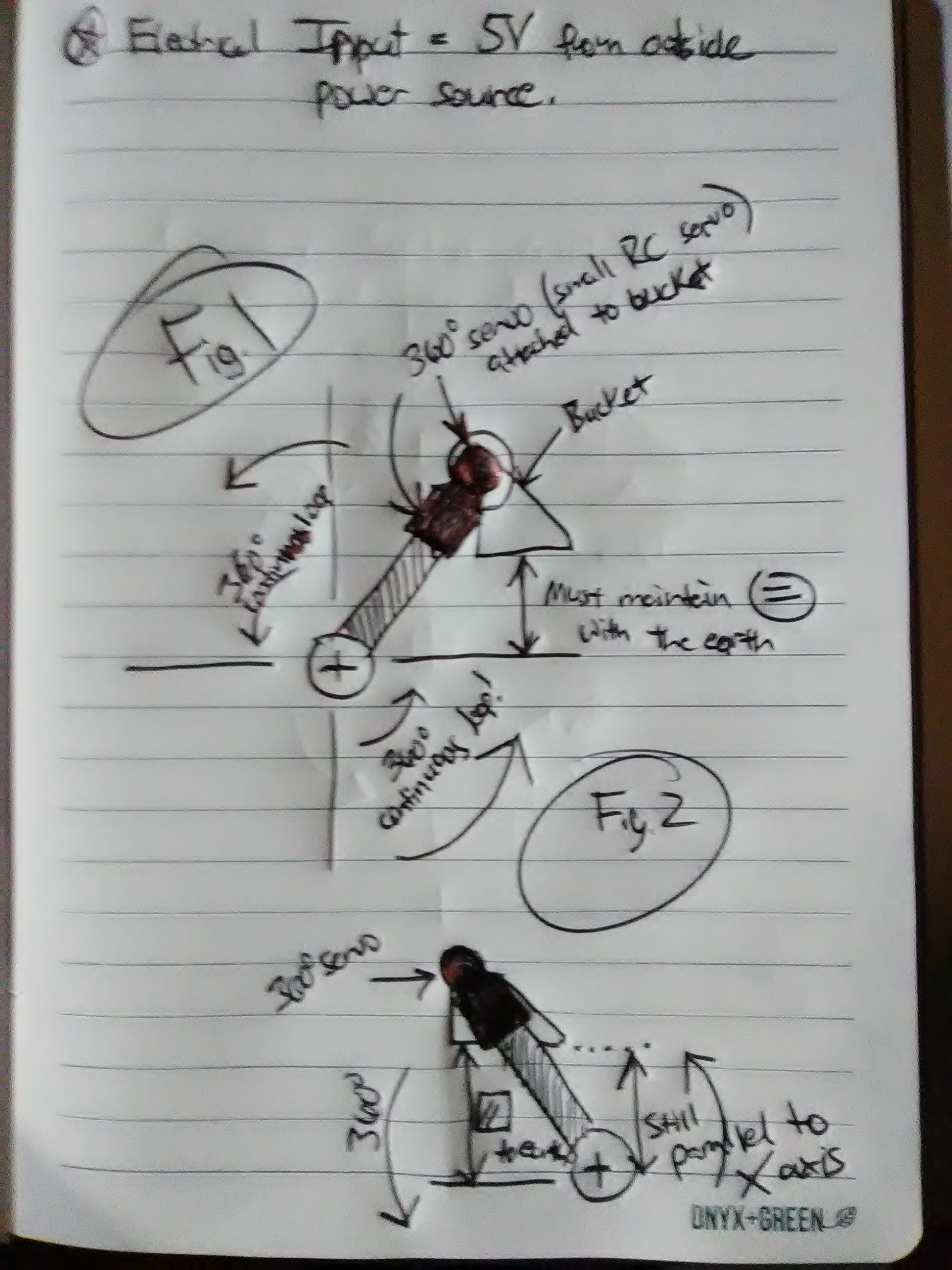
Sure. Please see the attached sketch and advise. Thanks Jim. VID_20181216_181902.3gp (1015.8 KB)
The drawing suggests that no motor, sensor or electronics are needed.
If the bucket hangs on bearings from a support axle directly above its center of gravity, it will automatically level itself.
if you look closer, you can see that I put 5 volt input to a single servo motor at the top of the page. I also denoted the servo location and direction of servo rotation as well. Let me send you another picture of the actual unit.
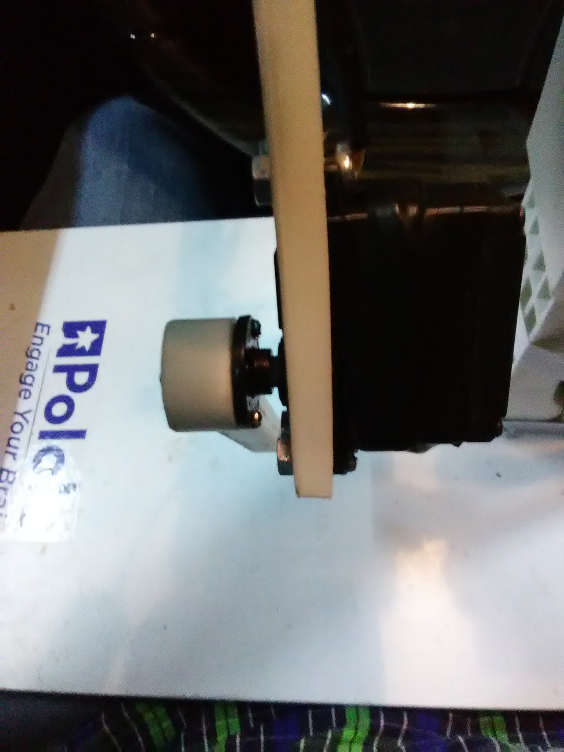
See pics. The bucket is not shown in this pic.
I just sent you some pics and a video. Right now I’m using a pololu a * 3 to you four and a mpu6050 to try and accomplish what I need to do. I also have a maestro mini 6 channel servo controller I can use as well.
I just sent you some pics and a video. Right now I’m using a pololu a * 3 to you four and a mpu6050 to try and accomplish what I need to do. I also have a maestro mini 6 channel servo controller I can use as well. Please advise. I got everything ready I just need to code knocked out
I need some help regarding the code for my 32u4 astar microcontroller. I currently have it running a continuous rotation servo where the servo is supposed to follow the movement of my mpu6050 gyro accelerometer. So the mpu6050 rotates 360 degrees continuously and the servo is supposed to follow it accordingly , degree by degree. However, consequently, what it does is it will follow the movement of the gyro all the way up to 180 degrees, then it reverses its direction and goes back 180 degrees to complete the 360 degrees movement. What I needed to do is I need the servo to continue to follow the gyro all the way through the 180 degree mark up to the 360 degree Mark and continue to do so. Can anyone help me out? thanks in advance
You will need a shaft encoder in order to make use of a continuous rotation servo, as there is otherwise no way to know how the servo shaft is positioned.
Since you will need an encoder, I would recommend to use a step motor or brushed DC motor instead of a continuous rotation servo, as you will have better control.
Yes, that is an option I suppose. However, I have seen numerous videos on YouTube of guys that have built self-balancing robots that just use modified 180-degree servos. None of them used encoders.
What is a “modified 180-degree servo”?
As you can quite easily verify, you have no control over the shaft angle of a continuous rotation servo, without using some sort of angular position feedback.
But is that not what you meant with this comment? “Fehler1977, post:12, topic:16271”: the servos are continuously rotating servos, and I don’t believe that they can accept angle input data.
@Fehler1977 I am not entirely sure about this, but it sounds like you might not be expecting the right kind of behavior from a standard servo modified for continuous operation. If you modify a standard servo for continuous rotation by removing its physical end stops and disconnecting its feedback potentiometer, you will lose the ability to control the position of the servo output (though the output will now be able to rotate 360 degrees). Just like when controlling a continuous rotation servo, modifying the pulse width of a hobby RC signal will allow you to control the speed of the output of the modified standard servo (and that servo will not have any way to tell how far it has rotated since its feedback potentiometer has been disconnected).
However, the behavior you’re describing sounds more like what I might expect from a 360 degree servo (like a sail winch servo), which does not do continuous rotation. Can you send a link to a datasheet or product page for the servo you are using?
-Jon