Hi, guys. Am trying to recreate the QTR-1RC from individual components. So far so good, got the schematics:
Coupled up an infrared LED to the 150k resistor you see on the left branch, inserted a 10nF capacitor between Vin and middle node, as shown in the pic, and a phototransistor on the lower branch that leads to ground. The output has the 220k resistor.
Problem I’m facing, when powering the circuit at 6V, the LED doesn’t light up. Am using a phone to test this. Also, if I take the LED alone and couple it in serial with a 1k resistor, it light up from the 6V power source (my battery holder)…
Any hints or stuff I’d need to be aware of?
P.S.: No, it doesn’t light up with a 150k resistor…
I’m glad to hear you got it working. Note that you might need to tweak your resistor values slightly to get a good response curve from your particular emitter/transistor pair.
If you have a microcontroller with an LCD or serial connection to a computer you can use that to determine the response curve just by passing your sensor over black and white surfaces at various heights and watching the output.
Okay, am going on the blind here. I got BabyO plugged in, the sensor should go on one of the PDs (PDx, x=1,2,3). What application should I be using to determine the response curve given the micro-controller is connected to the PC via the USB programmer?
Say I “attach” the sensor’s output to PD2. What would the steps be to get the sensor’s readings and based on those reading to control one of the 2 GM8 motors? Yeah, planning to make a line follower, been reading around, but as far as the programming goes, I found nearly zero resources. I need a good example apparently =\
Regarding the connections, I got the output of the PCB board you saw in the youtube video connected to PD2, while VIN and GND are tied to a different battery holder (than the one I used to power-up the micro-controller)…
I think I also need to make PIND = 1 (an output) or 0 (an input)…
One more thing - in the diagram of the QTR-1RC, the phototransistor’s small leg (catode) should be connected to ground or the upper node. Cuz to me the diagram doesn’t look right o_O…
Or put simply, on a phototransistor, which is which o_O Small leg (catode) is the collector or emitter? Thanks!
My thought was you could use a terminal program (e.g. hyperterm) to display readings as you transmitted them from your BabyO to the computer. You could then see what range of numbers you were getting for light and dark regions at various heights.
The steps to get the readings are detailed on the QTR-1RC web page: drive the signal line high for 10 us, turn the signal line into an input, and time how long it takes the input signal to go low. The time becomes an analog measure of the detected reflectance. Using this information to follow a line becomes much more complicated. Ideally you will want to have at least two sensors so you can easily determine if your robot is right or left of the line. If you have more sensors, you can compute a weighted average of the sensor readings to get an approximate position of the line under your robot, and then you obtain your motor speeds by using PID on this position.
We intend to do a detailed write-up on line detection and line following, but that might not be
“Driving high” means you should set the pin as an output and have it output “high”. This is done by setting that pin’s DDR bit to 1 and setting that pin’s PORT bit to 1. You would drive low by setting the pin’s DDR bit to 1 and setting the pin’s PORT bit to 0.
So initially you want something like:
_DDRD.B2 = 1; // make pin an output
_PORTD.B2 = 1; // drive pin high
_delay_ms(1); // hopefully this is long enough to charge your capacitor
_DDRD.B2 = 0; // make pin an input
_PORTD.B2 = 0; // disable internal pull-up (pin should now be high-Z)
now time how long it takes _PIN.B2 to go low (this should be on the order of a few milliseconds).
The PIN register contains the input value of the pin, so check _PIN.B2 rather than _PORT.B2. You use the PORT register to set the output state and the PIN register to read the input state.
At 20 MHz, the function _delay_ms() cannot delay for more than around 13 ms, so your _delay_ms(25) will probably not work right. I suggest you make your own delay_ms() function that repeatedly calls _delay_ms(1), or replace your _delay_ms(25) a sequence of shorter delays.
It sounds like you have a photodiode rather than a phototransistor. Try searching around for information on photodiodes and it should become clear how to use it.
Thanks for taking the time to reply to my questions, Ben. You are most honorable for that I’ve stood up all night building the chassis of the robot I intend to have follow a line, so I believe it’s time I posted some pictures.
Haven’t mounted the sensors yet, cuz I’m a bit blurred here. Am in a country where I can’t find photo-reflectors, even at electronics shops. And we don’t have RadioShack or other contraptions here
I have an IR LED (left) and a phototransistor (right). Now, based on the schematics, which is the emitter and which is the collector on the phototransistor? Or what I see in that diagram (the right branch) isn’t the phototransistor depicted in the right-side legend?
Thanks again! Your help is invaluable. I will eventually end up posting the project itself.
Back again, Ben. I managed to get the sensor going eventually. I chose to work with the analog version, but used different resistors. Photo-transistor (yes, it was a photo-transistor after all) goes with a resistor of 270 Ohms, while the IR LED with a resistor of 10 KOhms. The schematic looks the same as for the QTR-1A sensor.
I have a few issues and would like to hopefully solve them. I managed to find a threshold for the sensor and worked with the following code (taken from the example codelib):
#define F_CPU 20000000UL

#include <avr/io.h>

void analog_init(void)
{
	ADMUX = (1 << REFS0);
	ADCSRA = (6 << ADPS0);
	ADCSRA |= (1 << ADEN);
}

unsigned int analog10(unsigned char channel)
{
	ADMUX &= ~0x1F;
	ADMUX |= channel;

	ADCSRA |= (1 << ADSC);

	while (bit_is_set(ADCSRA, ADSC));

	return (ADCL | ADCH << 8);	// read ADC (full 10 bits);
}

unsigned int analog8(unsigned char channel)
{
	return(analog10(channel) >> 2);
}

int main(void)
{
        // Make sure all our registers are clear
        DDRB = 0;
        DDRC = 0;
        DDRD = 0;

	// Make sure all our pull-up resistors are clear
        PORTB = 0;
        PORTC = 0;
        PORTD = 0;

	int pot;

	analog_init();

	DDRD |= (1 << PD1);

	for(;;)
	{
		pot = analog8(0); // I connected the sensor to PC0

		if(pot > 254.9)
		{
			PORTD |= (1 << PD1); // if it detects black, light up LED
		} else {
			PORTD &= ~(1 << PD1); // if not (white), turn it off
		}
	}

	return(0);
}
This is taken from Tom Benedict’s analog-only example. Using that threshold gives good results BUT… If black color is detected (aka sensor is with LED and photo-transistor on the same side as the black line is), red LED at PD1 is on. If not, and white is detected, red LED starts to flicker very weak. I’ve also made a video, in which you won’t see it flicker though
Anything I can do with perhaps the resistors or analog conversion to make it shut off when white is detected?
Hmm, I think your sensor is not actually working the way you think it is. Let’s look at your code here:
pot = analog8(0); // I connected the sensor to PC0
if(pot > 254.9)
Note that analog8(0) returns an 8-bit value, so it will range from 0 - 255. You are setting your threshold to be 254. Obviously this is not so good. If the output is a solid 255 (black), you will have your red led on, otherwise it should be off. That you can barely get the analog reading to change from 255 to 254 is a sign that your sensor is not working the way you want and what you are observing could almost be attributed to noise present in the analog conversion.
I think a huge part of your problem is that you are using a 10k resistor for the IR LED. This is way too big. Your IR LED is so dim that there’s probably almost no reflected light for your phototransistor to detect. Notice that in our QTR-1A we use a 150 ohm (not kOhm) resistor for the LED. Try using a much smaller resistor and see if you can get your threshold value to come down to somewhere in the middle of the range (e.g. 128).
Before I go on, I must correct what I said earlier, lol. I’m using a 270 ohm resistor for IR LED and 10k resistor for photo-transistor Not vice-versa. My bad, I was probably in a hurry…
I’ll use what you suggested and I have to make a remark. It was NOISE I shut down the USB programmer and connected only the controller. Now I have these situations happening:
I have the sensor PCB oriented upwards, with LEDs striking out;
a] when I got nothing above the sensor, RED led is on;
b] when I move the paper at say 2-3 cms away from the sensor, with white on it, LED completely shuts down (doesn’t flicker anymore);
c] when I move the black duc-tape line over the sensor, it firmly lights up to powerful red;
I think I found my culprit Okay, time to make the one in the QTR-1A scheme and will post some feedback Thanks for bearing with me…
Watch this for me, should show what I’ve achieved so far…
You were right, Ben. That sensor’s got power, lol. I got it to sit very comfy at an average of 245. At 240 it starts flickering, while with any value past 245 it shuts completely off. I used the same code, and take it optimal value is ~247…
Well, that’s an improvement, but it’s still not very good. Having a threshold so close to an extreme means you have very little signal room to work with. Ideally white will give a very different reading from black, but in your current setup it seems like white is giving you something like 4.5 V while black is giving you 5 V. I think you should consider decreasing your IR LED resistor further (are you still using 270?) to make the LED brighter, and you should consider increasing the resistor between your phototransistor and Vcc. Try to get white to trigger the LED below a threshold of maybe 50 (something small), then flip the code so the LED triggers for voltages above the threshold and try to get black to trigger the LED above 200. If you can do that, you know you have a nice big difference between your white signal and your black signal, and that in turn gives you something that’ll be easier to work with.
Came back to report some changes I’ve tied 2 x 220 KOhm to the photo-transistor and 2x150 Ohm on the IR LED, as follows:
220 + 220 = 440 KOhms;
150 || 150 = 75 Ohms;
So now, the threshold is at around 190. That’s where the red led starts flickering. Below 190 red led is lit up, and above 190 is shut down (while holding the paper with white facing above the sensor).
Hoping this is OK. Awaiting your reply, Ben, so I know I can go on with this…

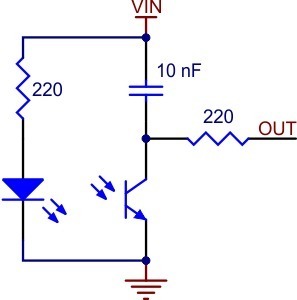
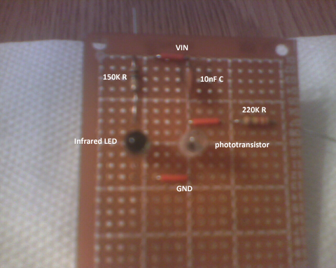
 Figure of speech. Funny thing is it worked with 1k…
 Hope this does the trick though…
 I’ve stood up all night building the chassis of the robot I intend to have follow a line, so I believe it’s time I posted some pictures.
 Thanks for bearing with me…