HELP with Save the program

You can try digikey (you want the surface-mount 32-pin QFN package), or you can buy some directly from us:

pololu.com/catalog/product/851

We don’t currently list any in stock, but if you backorder one (or a few, in case you want some backups), we should be able to ship it out within a day or two.

- Ben

Dear Ben,

I just placed the order.

Thank you very much,

Jose Carpio.

Hi Ben,

I have some questions:

If the problem is it the microcontroller, in my 3PI, you can send me only firmware of microcontroller?
Or, if I buy the new atmega168, you´ll be send it right to work?
Don´t have any solutions without that I send my 3PI?

Thanks,

Andre Luis

The microcontroller on the 3pi doesn’t have any firmware; it’s simply an ATmega168 that you can program with your own code. It sounds like the chip itself is damaged or in a state that makes it unprogrammable. You could replace the mega168 yourself, but I would only recommend this if you have the proper experience and tools for desoldering and resoldering a surface-mount IC. You can see the mega168 on the 3pi PCB… is that something you would feel comfortable desoldering? Do you know anyone who has the skills and tools to do it for you? If not, the only alternative I can suggest is sending it back to us.

- Ben

Dear Ben,

I just received the Atmel 168 Mega you sent me.

What I have to do after replace the processor? You told me I have to program some fuses? Can I do that in the same way
I save a usual program?

Thanks in advance,

Jose Carpio.

There are a few steps I recommend you take to test your rework job:

  1. The first thing you should do after you replace the chip is to test for unintended short circuits. Visually inspect all your solder joints (preferrably under a microscope) to make sure the connections look good and there are no solder bridges to neighboring pins/traces.

  2. Connect power and look for abnormally high current (note that the IR leds on the reflectance sensors will be on, which makes the total normal current draw around 100 mA).

  3. If everything looks good, connect your programmer and try to read the device signature.

  4. If this is successful, program the fuses using the following avrdude command-line instruction:

avrdude -p m168 -P COM9 -c avrispv2 -e -U lfuse:w:0xF6:m -U hfuse:w:0xDC:m -U efuse:w:0x01:m

You will need to change COM9 to the port your programmer is on (you can find this using the device manager if you’re running Windows). If you are using the Orangutan USB programmer, the programmer protocol of avrispv2 is correct. If you are using a different programmer, you might need to change this to something else (e.g. avrispmkii).

The fuse settings configure the brown-out detection level to 4.3V, unprogram the CKDIV8 bit so that the system clock is no longer divided by 8, and select for a full-swing 0.4-20MHz oscillator with 1K CK start-up time from power-down and 14CK + 4.1 ms additional delay from reset.

  1. Program the 3pi with the demo program that it ships with. You can find the hex file for this program in the the Pololu AVR library at the path:

libpololu-avr/examples/atmega168/hex_files/3pi-demo-program.hex

Run through the various demos in the program and make sure the 3pi behaves as you expect it to.

Please let me know how the repair goes, and ask if you have any questions!

- Ben

Dear Ben,

Thank you very much for the information.

I followed your recommendations. I replaced the Atmel MEGA168 and then I inspected the chip with 20x lens. After resoldered some joints, all looked correct.
Then I connected the power and the IR leds switched on, the LCD shown the same as before changed the chip, I mean, a line of black boxes. Finally I tried to read device signature with AVR Studio 4.16 Build 628 using Windows XP with STK500 and AVRISP programmers, showing allways the same error:

ISP Mode Error
A problem ocurred when executing the command. Make sure you are using the correct programming method. Current mode is ISP. See the command output for more info. …

I tried to execute avrdude command in Windows getting the following error:

D:\WinAVR-20090313\utils\bin>avrdude -p m168 -P COM9 -c avrispv2 -e -U lfuse:w:0
xF6:m -U hfuse:w:0xDC:m -U efuse:w:0x01:m


avrdude: stk500v2_command(): command failed

avrdude: stk500v2_command(): unknown status 0xc9

avrdude: stk500v2_program_enable(): cannot get connection status

avrdude: initialization failed, rc=-1

         Double check connections and try again, or use -F to override

         this check.


avrdude: stk500_2_ReceiveMessage(): timeout


avrdude done.  Thank you.

I soldered the ATMEGA168 manually. I have no access to a IR solder, so I am not sure if I over heated the chip.

This is a little bit frustrating situation because some students are waiting for the robot to continue with a project.

Any case, thank you very much for you time, for your fast and accurate answers and your attention.

If you have any suggestion about what I have to test now I will be very pleased to know.

Yours sincerelly,

Jose Carpio.

I’m sorry to hear that things still aren’t working. Are you using our Orangutan USB programmer? Have you verified that the programmer is functioning properly, perhaps by trying to program a different AVR-based device such as another 3pi? Can you use AVR Studio to determine the ISP frequency of the programmer (look under the Main tab of the AVRISP programming dialog)?

It seems to me like there are four possible things that could be wrong, so we should try to narrow down which it is:

  1. The mega168 is not soldered properly, leading to poor connections or shorts. Were you careful to align it so that pin 1 is soldered to the correct pad? Can you post a high-resolution picture of the mega168 on the PCB?

  2. The mega168 was damaged when you soldered it.

  3. There is a problem with the programmer.

  4. The programmer is set to an ISP frequency that doesn’t let it talk to the new microcontroller. Before you configure the fuses on the mega168, it is running at 1 MHz rather than 20 MHz, which means that some programming frequencies that work for a configured 3pi will not work for one that still needs to have its fuses set.

- Ben

Dear Ben,

I am using your Orangutan USB programmer. We buy a pack Pololu 3pi+Programmer. Before 3pi death I reach to programm two or three times. So I supose the programmer is working properly. I haven’t got at this momment another 3pi, sorry :frowning: I tried to change the ISP frequency of the programmer with AVR Studio. I changed the frequency without problems, but was not possible to program 3pi at any frequency.

About your options, that are my suggestions:

  1. Pic’s mark is in the same way as the picture you published in the web, left up conner (looking the boar front the opposite side of the LCD, with the center ball in the bottom). I checked first lines connections and looks fine. I will try to send you some pictures next week.

  2. That is possible.

  3. Will be possible, but I saved some programs with this programmer before 3pi death.

  4. Can I do something to solve it if I can’t save the fuses?

Thank you again!

Yours sincerelly,

Jose.

Did you make sure to press the “Write” button to apply the ISP frequency change before you tried to use the programmer on the 3pi? The goal would be to see if you can read the device signature at one of the lowest ISP frequencies. If you cannot, the problem is most likely due to a damaged or mis-soldered ATmega168, in which case I see your only options as (1) rework it further, (2) try replacing the chip again, or (3) send it back to us to take a look at. I would still be interested in seeing a high-resolution picture of the replaced mega168.

- Ben

Dear Ben,

I pressed the “Write” button after change the ISP frequency. I understand your solutions and next week I will try to replace again the ATmega168. If that last test doesn’t work I will sent you. I am sure you will find the solution. I will try to capture some images with the microscope and sent to you.

Have a good weekend!

Best regards,

Jose Carpio.

Please post a picture of your 3pi before you try to replace the mega168 a second time, just in case we can see something in the picture that might reveal the problem or keep you from duplicating a problem in your second rework. I hope you have a good weekend as well.

- Ben

Dear Ben,

I attached some pictures I took with the microscope. If you need a more general view, please tell me and I will try to take it with a normal camera.

Jose Carpio.


… and three more.

Jose Carpio.


… and the last three.

Jose Carpio.


Thanks for providing the pictures. The solder connections look pretty good in general, but some look better than others and there are a few places where it seems like there could be shorts. My suggestion would be to try improving the uglier connections to get them to look like the nicer ones (e.g. the ones on the left side of picture 7.jpg). You can clean up the connections by putting a small ball of solder on the tip of your iron and slowly sweeping it across the pins. If you do it right, they should all end up looking like the ones on the left side of picture 7.jpg.

Also, all of your pictures were pretty much looking down on the chip from directly above, but you should make sure to inspect the chip from an angle so that you can see what the connections look like from the side as well as from above.

What tools did you use to desolder the original chip?

- Ben

Dear Ben,

I am sorry for this time without answer. I replaced again the Atmel processor and good news!!

The programmer now can read the processor signature.

I executed the command you give me getting the following output:

D:>avrdude -p m168 -P COM9 -c avrispv2 -e -U lfuse:w:0xF6:m -U hfuse:w:0xDC:m -

U efuse:w:0x01:m

avrdude: AVR device initialized and ready to accept instructions

Reading | ################################################## | 100% 0.19s

avrdude: Device signature = 0x1e9406

avrdude: erasing chip

avrdude: reading input file “0xF6”

avrdude: writing lfuse (1 bytes):

Writing | ################################################## | 100% 0.17s

avrdude: 1 bytes of lfuse written

avrdude: verifying lfuse memory against 0xF6:

avrdude: load data lfuse data from input file 0xF6:

avrdude: input file 0xF6 contains 1 bytes

avrdude: reading on-chip lfuse data:

Reading | ################################################## | 100% 0.08s

avrdude: verifying …

avrdude: 1 bytes of lfuse verified

avrdude: reading input file “0xDC”

avrdude: writing hfuse (1 bytes):

Writing | ################################################## | 100% 0.17s

avrdude: 1 bytes of hfuse written

avrdude: verifying hfuse memory against 0xDC:

avrdude: load data hfuse data from input file 0xDC:

avrdude: input file 0xDC contains 1 bytes

avrdude: reading on-chip hfuse data:

Reading | ################################################## | 100% 0.06s

avrdude: verifying …

avrdude: 1 bytes of hfuse verified

avrdude: reading input file “0x01”

avrdude: writing efuse (1 bytes):

Writing | ################################################## | 100% 0.06s

avrdude: 1 bytes of efuse written

avrdude: verifying efuse memory against 0x01:

avrdude: load data efuse data from input file 0x01:

avrdude: input file 0x01 contains 1 bytes

avrdude: reading on-chip efuse data:

Reading | ################################################## | 100% 0.06s

avrdude: verifying …

avrdude: 1 bytes of efuse verified

avrdude: safemode: Fuses OK

avrdude done. Thank you.

-----------------------------------------8<------------------------------------------

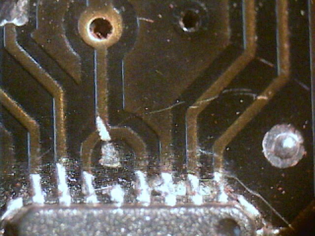
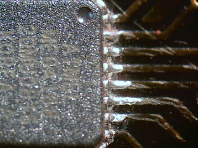
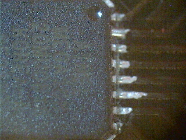
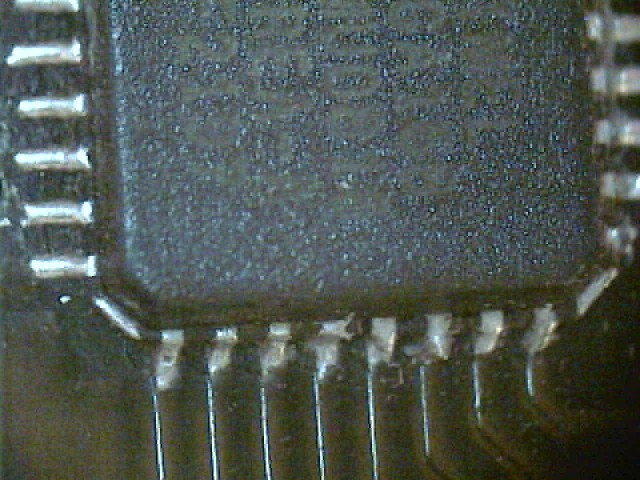
It’s looks perfect, however I tried to save a program and the AVR Studio give me the same error I reported you some days ago. I tried to put down the programmer speed but it doesn’t work.

Checking the ISP mode window I realise than the Oscillator Calibration Byte is fixed to 8.0Mhz and I have no other option.

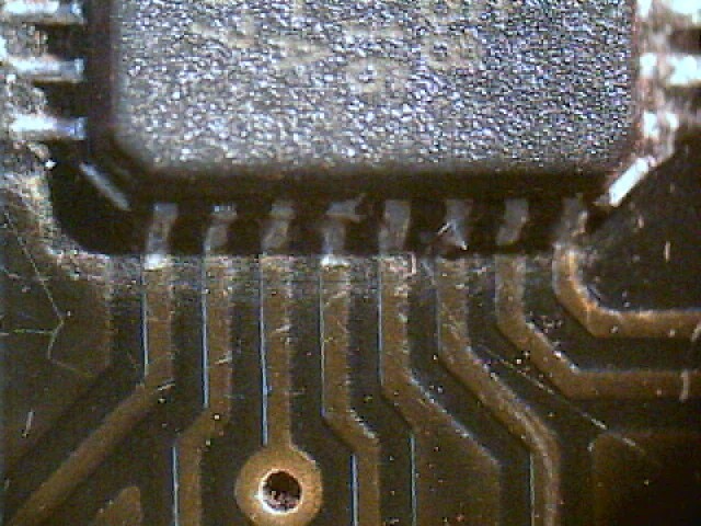
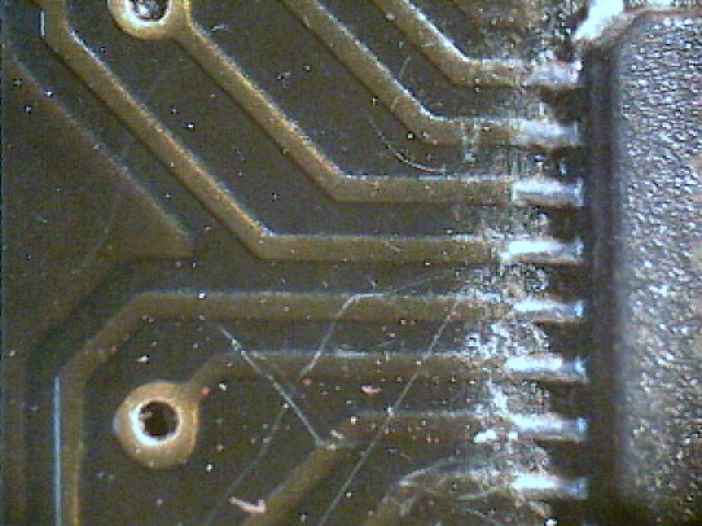
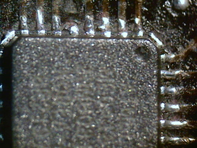
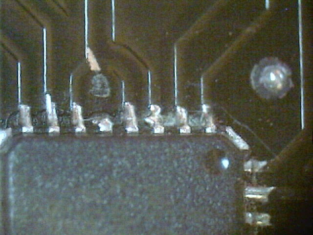
Any idea in order to finally repair the Pololu 3pi? Do you need more information than can help you to detect where will be the mistake?

Thank you very much in advance,

Jose Carpio.

Jose,

From your avrdude output, I’d say you at least partially fixed your 3pi: it seems like you don’t have any solder problems on the programming lines, and the AVR was at least briefly alive. Did you pay attention to the current draw when you powered up the 3pi to check for potentially damaging shorts between power and ground?

What happens if you run the avrdude command for a chip erase:

avrdude -p m168 -P COM9 -c avrispv2 -e

Can you remind me exactly what error you’re getting from AVR Studio (maybe post a screenshot)? Did your 3pi turn off while you were trying to program it this most recent time?

Don’t worry about the oscillator calibration value; this would only be important if the AVR was running off of its internal RC oscillator. Now that you’ve set the fuses, it should be running off the external 20 MHz resonator. But this brings up another potential source of your problem: if the resonator pins are soldered poorly (shorted or disconnected), the chip no longer has a clock source and it will not be programmable. You should use your microscope to inspect the connections on pins PB6 and PB7, and I suggest you use a multimeter to check for continuity from the AVR oscillator pads to the resonator pads. Finally, if you have access to an oscilloscope, I suggest you look at the resonator outputs to make sure it’s actually working.

- Ben

Dear Ben,

It’s a pleasure to coomunicate to you that Pololu 3pi is working again!

I did that you told me, I tested again the PB6 and PB7 conections and finally a change to higher than 5Mhz programming frecuency was necesary with AVR Studio.

I saved PID Line follower program and Pololu 3pi looks like new.

Thank you very much for your support.

I have a last question to you. Will be possible to make a simple modification to the Pololu 3pi in order to avoid the possibility to save a program with low battery?

Jose Carpio.

That’s great! I’m happy to hear that you’re back up and running. You should try to test out all of the 3pi’s features to make sure your connections are good between all of the ATmega168’s pins and the board.

The programming frequency needs to be less than 1/4 the target frequency, so it should be under 5 MHz. Note that the Orangutan USB programmer has a maximum ISP frequency of 2.5 MHz, and the frequencies listed in AVR Studio are not correct for the Orangutan USB programmer. The programmer user’s guide has more information about this.

You will also run into problems if you have your programmer set to the lowest ISP frequency as AVR Studio times out while waiting for the device to program. I think this might have been the cause of your problem.

The 3pi gives you direct access to the ATmega168 microcontroller via its programming lines, and the mega168 can get corrupted if it loses power during programming. That’s why it’s important you avoid programming the 3pi when its batteries are low, since low batteries increase the chances that power will cut out unexpectedly.

The Orangutan USB programmer tries to detect when power is lost and abort programming, but unfortunately, the very act of putting voltage on the programming lines can put enough voltage on the Vcc lines to keep the programmer from detecting that the voltage is unacceptably low for programming.

We are working on a second-generation AVR programmer that can more accurately and quickly detect when the target voltage is unstable or too low, which should better prevent (if not completely prevent) situations like this.

- Ben