Hi,
I’m trying to use a dual MC33926 to drive a robot.
I have used other motor drivers like L298 before but this seems to be quite different. I have followed the instructions on the web site but it does not seem to work. The motor doesn’t rotate.
My code is below (arduino)
const int M1D1PWM = 6; //Hold low
const int M1D2PWM = 5; //Used
const int M1IN1 = 9;
const int M1IN2 = 11;
const int ENABLE = 10;

void setup() {
  // put your setup code here, to run once:
  pinMode(M1D1PWM, OUTPUT);
  pinMode(M1D2PWM, OUTPUT);
  pinMode(M1IN1, OUTPUT);
  pinMode(M1IN2, OUTPUT);
  pinMode(ENABLE, OUTPUT);
}
void loop() {
  // put your main code here, to run repeatedly:
  digitalWrite(ENABLE, HIGH);
  digitalWrite(M1IN2, LOW);
  digitalWrite(M1IN1, HIGH);
  digitalWrite(M1D1PWM, LOW);
  analogWrite(M1D2PWM, 180);
}
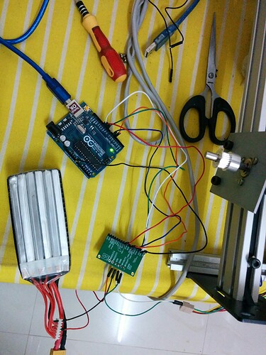
I have attached a pic on how the the setup is wired up.
Can you help me resolve the problem?
Damn sorry, I made a stupid error. D1 pin is 5 and D2 pin is 6, when I connect it that way it works fine.
If I may ask another question: The website states that we can use M1IN1 and M1IN2 as PWM pins instead of D1 and D2. How would that work, and is it any different from what we have done here?
Hello.
Thank you for letting us know you figured out the problem and fixed it.
The MC33926 motor driver will operate in drive/brake mode if PWM signals are applied directly to the two input pins (IN1 and IN2) and drive/coast if PWMing either of the disable lines (D1 or D2). To use the IN1 and IN2 pins, you PWM one IN pin to drive in one direction and PWM the other IN pin to drive in reverse. The truth table in the MC33926’s datasheet on page 17 shows this and other input configurations and their expected outputs. You can find that datasheet under the “Resources” tab on the dual MC33926 motor driver’s product page.
- Amanda
Thanks, I tried that out and it worked.
What is the difference between drive/brake and drive/coast, and which one to use? My application is like this: the motor lifts a heavy load for 10 cm, then stops for a minute, then again lifts it by 10 cm, and so on.
As you probably know, a PWM signal is used to control a motor’s speed by quickly switching the supply voltage to it on and off. The difference between the two operations is what happens to the motor leads during the off phase of the PWM. In drive/brake mode, the motor leads are shorted together through the motor driver causing the motor to act as a brake. In drive/coast mode, the power is removed and motor leads floating allowing the motor to coast.
From your brief description, there is no clear indication which operation would be more appropriate for your application. We generally recommend drive/brake operation over drive/coast since it provides a more linear relationship between PWM and the motor speed.
- Amanda

