I am attempting to use the Romi in a robots course. I have 10 Romi chassis and 10 arm kits, along with Raspberry Pi’s and lots of batteries. It has taken two orders to get here so far and I still think I might still be missing required components. I have 3 issues…
-
In the arm assembly instructions it states that 6v is the max and that the Power Distribution Board can be configured for the 4 battery option. However, I am using the 32U4 Control Board and can’t determine if it has this power problem and, if so, how to configure to use 4 batteries or an alternative solution. Perhaps power should come from the Pi?
-
I can’t find instructions on actually connecting the arm to the controller, or does the arm get connected to the Pi for control.
-
In the arm assembly instructions, step 3.2 it says
“Install the gripper pinion gear on the micro servo using the included screw and use your servo controller to command the servo to the fully closed position (2400 µs pulse duration)”.
There is no more info on how to do this. Do I use the Pi as the controller? Do I need another piece of equipment to initialize the servo?
I have searched for 2 days with no results and I need help getting this arm working. I am a software guy who has used Pi’s for many projects, but I can’t find the info needed to get started.
Thanks
Further research reveals that the 32U4 Control Board is an Arduino board capable of controlling servos and it has regulated 5v outputs, so questions 1 & 3 are answered (controller and power). Question 2 is a bit less clear. It seems there are free i/o pins (0, 1, 5, 12, A0, A2, A3, and A4). The arm needs 3 pins, so I’m thinking 0,1,and 5.
I’d like to suggest that the Arm Kit user guide (maybe at section 3.2?) includes links to the multiple areas of the 32U4 guide, since I suspect that this is a very common combination. This was fairly easy to access once I knew where to look.
As I suspected - the i/o connections for the arm to board need some documentation. There are obviously 3 servos on the arm. However, it seems there are only 2 free PWM pins (5 & 12). Section 3.9. Adding electronics says pin 12 will conflict with the buzzer. and to disconnect the buzzer requires cutting a board jumper. These boards are for a class and disabling a feature means it can’t be used in the future if wanted. Other PWM pins can be freed by giving up other functions.
A standard Mega AVR has 14 pwm pins available. I count 11 in the 32U4 pinout docs. This board does not seem to fully support the Arm Kit. I feel a but duped by the Pololu docs for the Romi/Arm Kit combo. There are no clear docs to connect the arm and the arm requires disabling other board features.
I don’t know how to best proceed. I’ve spent the money for these kits but is not a good product for a classroom.
I am sorry you are having trouble getting started with the Romi Arm Kit. As noted on the Robot Arm Kit’s product page, we are working on electronics to simplify integrating this arm into your Romi robot, but we did not want that to hold up releasing the arm itself for ambitious users with the skills to assemble their own electronics for powering and controlling the arm.
I have addressed your original 3 questions in some more detail below:
-
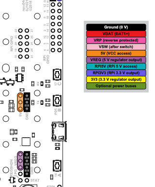
6V is the maximum of the nominal voltage range (which would be 4x AA batteries). The Romi 32U4 Control Board uses the 6-battery configuration. While you could tap into the battery contacts to get power from the 4x batteries, that would cause your batteries to drain unevenly, so you might consider adding the D24V22F6 regulator so you can power them from all 6 batteries, as mentioned under the “Powering the servos” heading of the “Using the Robot Arm for Romi” section of the user’s guide.
-
You can control the servos from the Romi 32U4 Control Board (more information about this is in point #3 below), but we do not have any specific examples for doing so. You might be able to control the servos from the Raspberry Pi instead; however, since it is more difficult to do tasks requiring precise timing with the Raspberry Pi, it would probably be more advantageous to use the Romi 32U4 Control Board. Also, we have not tested those particular servos with a 3.3V signal, so we can not guarantee it would work with signals from the Raspberry Pi without some kind of level shifter, but it would probably be okay.
-
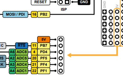
If you use the Romi 32U4 Control Board to send the servo signals, you can use the Arduino Servo Library, as you mentioned. The writeMicroseconds() function allows you to specify the pulse width of the signal. However, please note that the Servo library uses Timer 1, which conflicts with our Romi32U4Motors library. You can fix this by modifying the Servo library to use Timer 3 instead; instructions for doing this can be found in the “Controlling a servo” section of the Romi 32U4 Control Board user’s guide. The Servo library does not need to use PWM pin; any digital pin will work. Your idea of using 0, 1, and 5 should be okay. If you are using a Raspberry Pi, you probably aren’t using the LCD, so you could repurpose pins 11 and 4 as well.
Brandon
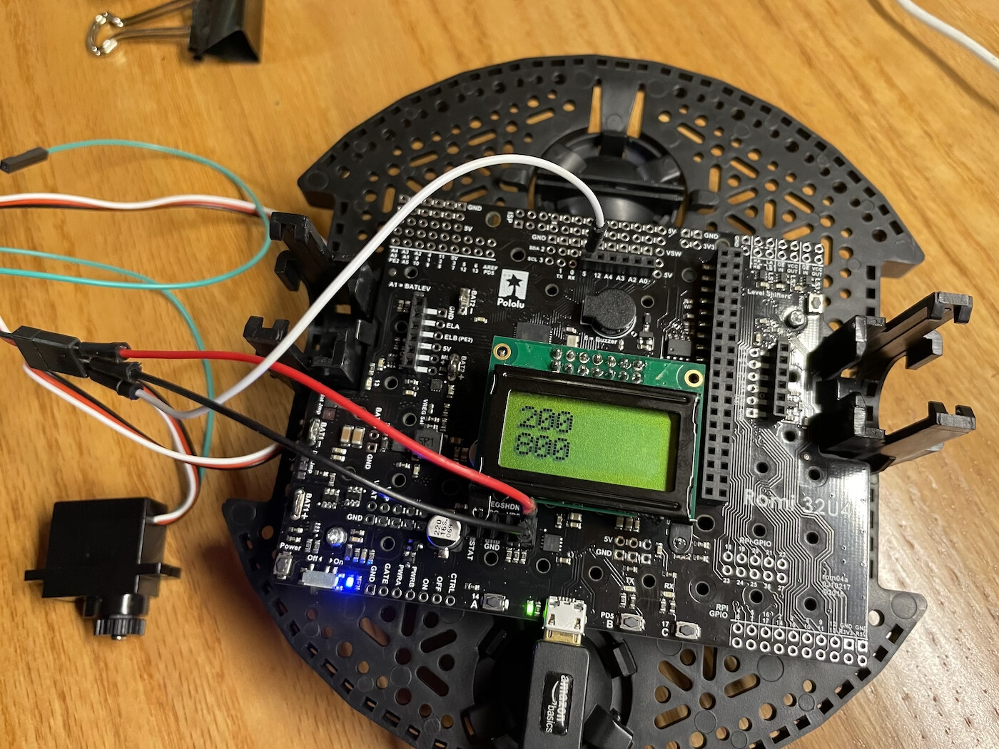
Here is code that should move between 200 µs and 800 µs 4 times, displaying on the lcd the current wave length. The servo control line is connected to pin 5 on the 32U4. Power is connected to a VREG 5v pin and ground. The servo never moov es. I suspect I have the wrong pin defined in the code. Any ideas?
#include <Servo.h>
Servo myServo;
int servoPin = 5;
int count = 0;

#include <Romi32U4.h>
Romi32U4LCD lcd;
int delayTime = 1000;

void setup() {
  myServo.attach(servoPin);
}

void loop() {
  if( count < 5 )
  {
    lcd.clear();
    myServo.write(200);
    lcd.print("200");
    delay(delayTime);
    lcd.gotoXY(0, 1);
    myServo.write(800);
    lcd.print("800");
    delay(delayTime);
    count++;
  }
  else
  {
    lcd.clear();
    lcd.print("done");
    delay(delayTime);
  }
}
Thanks for the info. Is there a reason I should not use the VREG 5v source on the 32U4? Prior to see your response I had just posted my attempt at using pin 5 to control the servo and it did not work. Are the pins renumbered somehow?
Thanks for the help. It was very useful.
The VREG pins did not measure any voltage when tested. I found in the docs that VREG power can be turned off with the power switch. It was off. I thought this was power to the entire board. I switched it on, verified 5v available, and still no movement. So I swapped to the larger arm servos and everything worked fine. I can sweep between 2400 and 600 with no problems. So it appears I have a bad servo.
In case anyone is interested here is that sweep code with the proper ‘writeMicroseconds’ calls.
#include <Servo.h>
#include <Romi32U4.h>

Servo myServo;
int servoPin = 5;
int count = 0;

Romi32U4LCD lcd;
int delayTime = 1000;

void setup() {
  myServo.attach(servoPin);
}

void loop() {
  if( count < 5 )
  {
    lcd.clear();
    delay(delayTime);
    myServo.writeMicroseconds(600);
    lcd.print("600");
    delay(delayTime);
    lcd.gotoXY(0, 1);
    myServo.writeMicroseconds(2400);
    lcd.print("2400");
    delay(delayTime);
    count++;
  }
  else
  {
    lcd.clear();
    lcd.print("done");
    delay(delayTime);
  }
}
Hello,
I just want to chime in and say that we got these working. We are using the WPILib implementation of the Romi software. ALl of our major controls are run through a websocket through the pi which uses I2C to control the 32U4. We are also using 6 batteries with the Romi because of the power constraints listed below (among other things).
Since we are using a raspberry pi, we needed to use VSW for the servos (with an external voltage regulator of course). We could run one servo fine, but too many and the Pi would brown out. The 5 volt converter did not have enough current to support the Pi and the servos. Sometimes we could get two running at a time, but in general, it would disconnect every time we tried more than one.
Hello, wmatchett.
I noticed in your pictures that you have the power to your servo connected backwards, which will usually damage the servo. If you correct this and it is still not working, then the servo probably needs to be replaced.
The updates to your code look better to me as well. In particular, the write() function of the Servo library treats values less than 544 as angles in degrees, which gets mapped from 0-180 to 544-2400 (in microseconds), so your myServo.write(200) in the first code is actually the same as myServo.write(2400) or myServo.writeMicroseconds(2400). I generally recommend using myServo.writeMicroseconds() to make sure you are getting direct control over the pulse width.
Also, if you have not done the modification to the Servo library that I mentioned in my first post, I recommend doing that before moving forward, otherwise it will interfere with the motor functions in our Romi32U4 library.
MrRSquared, thank you for chiming in with your experience. I noticed you posted a much more detailed thread about your setup, so we can continue the discussion about that there.
Brandon
1 Like
I’m not sure what you are looking at, but ground is on the pin row closest to the board edge, VREG is on the inside row. The power is correct in the pics. I made the library changes to timer3 before starting this post.
It is not the board where they look reversed, it is the servo. These servos are wired…
-+s
That way, if you plug them into the typical hobby servo ports backwards, you do not short the + to -.
I am not sure how difficult it is to access through the arduino software, but I highly recommend the headers WPILib uses.
You need to run a jumper from the 5v pin to the power rail, but then you can plug the servos in directly because it mimics the typical servo connector.
We used female headers (because most of our stuff is Vex and has male pins), and used male-male pins for the Gripper and arm servos. I think The FRC boards come with male pins.
This sounds great - do you have a source for these headers?
Pololu sells a bunch of them. If I were only concerned about the arm kits, I would buy black, red, then another color (usually most kits use yellow) for the respective pins -+s. Then, I would buy this to power the 5v rail (which needs to be connected to a power source to work. There happens to be a pin available right there. It is almost as if Pololu meant for this to be the setup  ). However, since we are using the pi to run our robot, we are not using the 5 volt pin to power the rail as it does not supply enough current (see my other post about that). In addition, we also have the Vex parts which all have mail pins. In that case, we are looking at these. For the Romi we have currently, I just cut up some female headers we had laying around. But for the future, this is probably what we will be using.
The 5V pin that MrRSquared suggested using is from the onboard regulator, which cannot handle the current from all three servos when they are under a significant load, so I would recommend the external regulator option I mentioned in my first post for powering that rail. Otherwise, loading the arm could result in a brownout and reset your robot.
By the way, the header for those pins comes already soldered on the Romi Robot Kit for FIRST.
Brandon
2 Likes
Thanks. I did not know if the 5v pin could handle the current without the raspberry pi. We certainly experienced the brownouts with a pi. One servo was fine. Two servos were iffy, Three were certainly right out.
I can confirm that three don’t work. Two work good - but this is with very fresh NmHi 2600mAh batteries.
I had no problem with 3 using a buck converter powered through vsw. I ran that power to the 5v rail and the ground to the ground rail.
Yes, an external, non control board power supply will power several servos.
True, but VSW is powered by the batteries on the Romi. I used a huge buck converter to test, but have a much smaller one for the students. I think it will work. Check my other thread for more details.