I have a Pololu JKR and a 499:1 Metal Gearmotor 25Dx58L mm LP 6V with 48 CPR Encoder.
I have read threads by Brandon M tech support from Pololu. This thread in particular.
Following his example for calibrating the feedback. However i’m unable to calculate the maximum due to the fact that my counts a period is 0.0216.
with my motor being 11RPM, the revolutions per milisecond is 0.00018. with 10ms being PID period
Ill get 0.0018 counts per revolution.
multiplying that by the counts per revolution being 12 due to the CPR encoder, ill get 0.0216 in each PID period.
To my understand the neutral being 2048. The maximum should be 2048+ 0.0216 . However the JKR utility doesn’t allow that low of a value to put into the software.
Am i getting this right? or is my calculation totally off?
I suspect something went wrong in your calculation; our 499:1 25D LP gearmotor with encoder should give many more encoder ticks than that when rotating at 11 RPM.
The encoder will output 12 ticks to the jrk each time it completes a revolution, and since the encoder is on the extended backshaft, you will need to multiple by the gear ratio to determine the number of ticks per revolution of the motor’s output shaft. After that, you can multiply by the RPM to get the number of ticks the jrk will read per minute. Then, you can convert this to the number of ticks per 10ms PID period. Here is each step in my calculation:
Number of ticks per revolution of the output shaft :
12 × 498.87 = 5986.44

Number of ticks per minute :
11 × 5986.44 = 65850.84

Number of ticks per second :
65850.84 ÷ 60 = 1097.514

Number of ticks per 10ms PID period :
1097.514 ÷ 100 = 10.97514
Since the jrk can only count full ticks, this can be rounded up to 11, which leaves you with a minimum of 2037 and a maximum of 2059. If you want a larger range of feedback, you might consider increasing your PID period (e.g. changing the PID period to 50ms will change the minimum to 1993 and the maximum to 2103).
i’ve set my maximum current limit to 2.4amps as my motor produces it’s maximum torque at 2.4A. But what value do i put for the current calibration? as i want a accurate current reading for monitoring purposes.
Another question, i want to count the ticks from the encoder using arduino. Assuming i take the signal from channel B of the hall sensor and connect it to my arduino. Is the calculation the same as you calculated for me?
Number of ticks per revolution of the output shaft :
12 × 498.87 = 5986.44
and if i need channel A and channel B from the encoder. can i duplicate the signal? meaning i duplicate channel A into two, one going into JRK and another going into my arduino is that possible via a breadboard?
The current is reported as a value from 0-255; this number gets multiplied by the current calibration value to convert it to mA. The default value (37 for the jrk21v3 and 149 for the jrk 12v12) should generally not need to be changed unless you measure the current and determine that the jrk’s numbers are inaccurate.
The number of counts you get per revolution will depend on how you are measuring it. Arduino interrupts can be set up to distinguish between high and low transitions, so if you are counting each change (instead of only low-to-high transitions), you will get twice the number of ticks per revolution.
It should be fine to split your channel A signal into two and read it from both the jrk and Arduino.
By the way, is there a reason you want the Arduino to monitor the signal separately? Depending on what you are trying to do, one solution might be to use the “Variable Reading Commands” to read the scaled feedback value from the jrk and use that to determine the speed it is reading.
Thanks again Brandon for the speedy feedback. Yes im already using the command variables to determine speed and such. But the counts is mainly to do angular movement, i want to move and stop the motor at certain angles. And im using arduino to pair up with MATLAB to design a graphical user interface.
Hi there Brandon, I have another problem which needs your help.
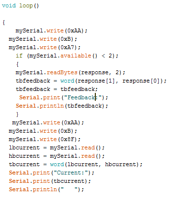
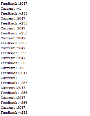
Im able to obtain the feedback reading through the jrk using my arduino and the value is correct, and if i read the current reading solo without the feedback code it gets the right value as well. However when i try to obtain them both at the same time the values are wrong. Mind having a look.
Thank you for posting your code. I suspect you are trying to read the return bytes before the jrk has a chance to process the command and return the corresponding bytes. You might try adding a small delay (maybe 50ms) after sending the get variable command to see if that fixes it.
Alternatively, you could try putting a while loop that waits for the response bytes just after sending the read variable command. For example: