Fast line follower with products from Pololu

Hello dicsum,

As Ben says, the 3pi robot user’s guide is very helpful, so we have benefited from it. Also you should check to the following links.

PID equation:
bestune.50megs.com/typeABC.htm
I have used PID equation in “type A” with only P and D term in our robot. The I term is not necessary for the line following algorithm.
e: Error reading from sensors
CO: PWM duty cycle for motors

A completed robot:
elm-chan.org/works/ltc/report.html
Good explanation of PID equation and analog sensors reading with source code.

Analog sensors setup:
micromouseonline.com/blog/20 … periments/
micromouseonline.com/blog/20 … ors-setup/

Cenk

Hello cenkk,

That desktop line follower looks very cute on that table! I’m curious about your drive train. Are the wheels being turned by motor shafts applied to the tires?

- Ryan

Cenk and Ben Thanks.

Sorry for my bad English.

I recommend that you review the web sites.
I wrote some code in some PID. I could not but be successful, especially in return. My program was more successful than previously. Even though I did not get the results you want great lengths. I took my time PID control. I was very tired.

Can I just wonder if the PID control routine Cenk? You look at the program for the problem easier to solve.

Features in the following way:
QTR-8A sensors card
motor speed: 1000 rpm
programming language: picbasic
microcontroller: 18f252
PWM frequency: 20000 Hz
Clock frequency 10Mhz

thank you.

Can you share your robots codes?
thanks, and good work

Hello to all,

Have you already study the codes written by Pololu and ChaN?
According to you, are there any missing points or mistakes on them? I don’t think so.

There are no magic codes available to get to drive any line follower robots. The codes depends on the design of robot. Also the design depends mostly on the running track. Actually our robot is not complicated, it is pretty simple.

In addition to my previous post:

  • Choosing the right motor controller IC:
    To get the robot to be reactive, the motor driver IC should brake the motors when the PWM signal goes low. Please have a look at the control function table in the file below.
    pololu.com/file/0J86/TB6612FNG.pdf

  • A new method for us to calculating error:
    Daniel Alvarez from Spain uses a linear interpolation function for very accurate error estimation. We will try it definitely.
    dani.foroselectronica.es/category/robotics/

We are planning to use on our next robot as different from on this robot:

  • Pololu 42x19mm Wheel and Encoder Set
    By using encoders we will try to teach to our robot where are the turns and what should be the speed on each turns.
    pololu.com/catalog/product/1218

  • Pololu Adjustable Boost Regulator 4-25V
    It is definitely necessary to remain the PID parameters valid during almost all the battery life.
    pololu.com/catalog/product/799

  • Pololu Pushbutton Power Switch SV
    We get bored with mechanical switches.
    pololu.com/catalog/product/750

  • And finally a 32 bit microcontroller:
    We need a powerful MCU to make the PID and error calculation functions to be faster. We will use a ARM7 based header board with easy to use libraries. The Espardino micro2148 board has a LPC2148 MCU with 60 MIPS, 32K RAM and 512K flash (Woow…).
    espardino.com/

Cenk

Hello RyanTM,

I have to ask you to excuse me that I haven’t noticed your post before.
Yes, you are totally right, the motor shafts applied to the tires on the desktop line follower robot. But it is not our robot. It builded by ChaN from Japan as already stated at website. This robot is just a reference for us.

Cenk

Nice work! Thanks for posting.

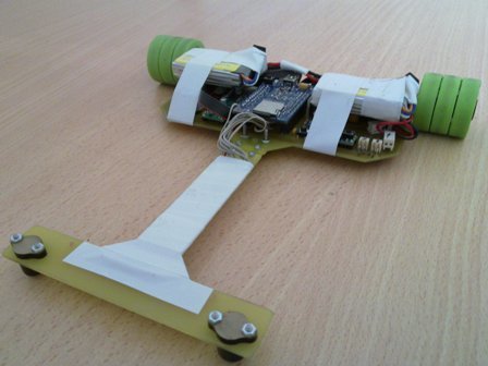
Here is the new champion of Turkey.

Speed: 1.9m/s
Turn radius: 25cm

IT IS:
Powered by Pololu
Pololu TB6612FNG Dual Motor Driver Carrier with paralleled outputs for each motor
Pololu QTR-8A Reflectance Sensor Array
Pololu Pushbutton Power Switch SV
Pololu Mini Metal Gearmotor Bracket Pair
Pololu Ball Caster with 3/8" Metal Ball

Powered by Espardino micro2148
ARM7 board based on LPC2148
http://www.espardino.com

Powered by Banebots
BaneBots Wheel, 1-3/8" x 0.4", 1/2" Hex Mount, 30A, Black/Green
http://banebots.com/pc/WHB-WS-144/T40P-143BG-HS4
Hub, Hex, Series 40, Set Screw, 3mm Bore, 3 Wide
http://banebots.com/pc/WHB-HM-HS4-M3/T40H-SM33

Powered by Maxon motor
Maxon 144325 - 12V, 2700 RPM

Congratulations on winning! Thanks posting the video and thanks for posting the parts list here, it’ll be a nice resource for someone trying to clone your bot or make a fast line follower.

How did you like the Espardino micro2148 board?

I’m asking because in a future robot you could probably replace your two TB6612FNG carriers, your Espardino, and your pushbutton power switch with a single Orangutan SVP-1284. The SVP has two TB6612FNG drivers built in to it, so you would be able to get the same performance out of your motors. The only thing is that the ATmega1284 (running at 20 MHz) is less powerful than the processor you used, so I’m wondering if you needed that power and what you used it for.

–David

LPC2148 is a 32 bit 60MIPS MCU with 32K RAM, and Espardino supports microSD/SDHC cards. All the calculations on my code take just 125 microsecond on that MCU. It means I read the line 4 times in every one milimeter. I think a 8 bit 20 MIPS MCU can run the same code within 750 microsecond. Besides I log some important data in the 32K of RAM without effecting the normal operation of the robot and then dump it to a microSD card and then analyze it in the computer. This is very useful for debugging and finding out some bugs.

I burnt one of the motor drivers when the motor got stalled last week and I could easily replace it with a new one. So, Orangutan SVP-1284 Robot Controller is not suitable for me because I am not able to solder some SMD parts. When they are seperated parts, I also can replace the motor drivers with which are more powerful than them if I need . Besides I can place the parts on the body more properly than a single big package.

Espardino + two TB6612FNG carrier + pushbutton cost $75, but an Orangutan SVP-1284 Robot Controller costs $90. Everytime I need more power at low cost :slight_smile:

I think you could probably replace two MCUs on your controller with a powerful MCU like based on ARM7 :slight_smile:

Hello.

Thanks for sharing your project. That course looks quite elaborate and exciting! What happens if two robots are almost the same speed and collide at the end?

- Jan

The race starts again at the start point if both of them lost the line after the collision. If that happens again, the robot which lost the line after its rival wins the race.

elm-chan.org/works/ltc/report.html

Did you use Led_on pin of QTR-8A to cancel ambient light like in the link below?
Thanks.
elm-chan.org/works/ltc/report.html

Each LED is wired to one MCU pin in ChaN’s design. He scans the sensors in sequence to cancel the ambient light by sampling the output voltage, turning on the LED, sampling again the output voltage, turning off the LED and getting the diffence between the two samples for each sensor.

The LEDON pin of the QTR-8A can be used for turn on/off all the LEDs in configuration four strings of two. It is just for power saving. Have a look at the schematics.
pololu.com/catalog/product/960

Actually it would be nice if Pololu would produce a sensor board that supports control each LED individually (preferably driven by a shift register to save pins on MCU).

Our LED on/off control is not just for power saving. You can turn off all the LEDs, read the sensor values, and then turn them on and read the sensor values. Having the LEDs paired up in series also halves the current you need to use for the LEDs.

Have you done any tests on individual LED on/off control compared to turning them all on and off at the same time?

- Jan

You are totally right in case the ambient light comes only from any source of light that is not a sensor of the array.

Unfortunately I can’t do any tests because I use only your QTR-8A. I am sure that you have done some tests on design stage of your sensor arrays. Any advice?

Sorry, I’m confused. I thought you said earlier that you did have individual LED control in your setup. I have never done a comparison, and a single control line for all LEDs has worked fine as far as I could tell.

- Jan

I think it is not important to onn-off all leds seperately. Because ambient lights come from sun or other IR sources.

Did you connected li-po batteries in series? Am I right they are 7.4V li-po batteries?