DRV 8835 chip dying out. Urgent help requested

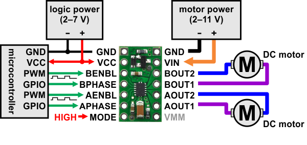
Hi there, my group of friends and I are trying to create car with 4 motors, controlled by a raspberry pi. We are using this chassis and motor kit. And we are using a raspberry pi 3 model B. This is the GPIO schemtaic for the pi we are using. We are using the DRV8835 to control our motors. There are two motors on each side of our car, the positive/negative leads to each motors are tied together on each side, which means we are running 2 motors in succession on each side. The motor supply is currently composed of 6 AA batteries, giving us 9V for our motor power supply. Everything else is connected exactly as shown in this diagram: DRV 8835 Phase/Enable Diagram Connections. GPIOs 5 and 12 being used as the inputs for Motor A, and GPIOs 6 and 13 being used as the inputs for Motor B. 12/13 are PWM inputs, and 5/6 are direction inputs.

Our car was working fine. We used the libraries provided by Polulu to drive the motors, and we tested the motors. Each motor worked fine, forward, reverse, left turn, and right turn all worked fine. We then created functions for these and we were then able to control the car using a WASD input on the keyboard to move forward/backwards etc.

Our car was working fine until eventually the driver wasn’t giving power to one side of the car, so only one side’s wheels were moving at all. The driver is still giving the same output and we are unsure of what to do so that we don’t blowout any remaining DRV8835’s.

This is our first robotics project so we do not 100% know what we are doing correctly/incorrectly. We were just starting to get some autonomous control down, when our driver stopped working out of nowhere, so now we are scurrying to get our car working again. We have 3 extra DRV 8835’s so we really don’t want to mess up again. The problem did occur when we had an HC-SRO4 sensor attached to the pi, which was connected correctly because we were correctly sensing distance. I’m not sure if this could have been the problem or not. If any more information is required don’t hesitate to ask. Any help or advice is greatly appreciated as we have deadlines coming up, and we are amateurs in robotics, but we are completely willing to learn everything we can.

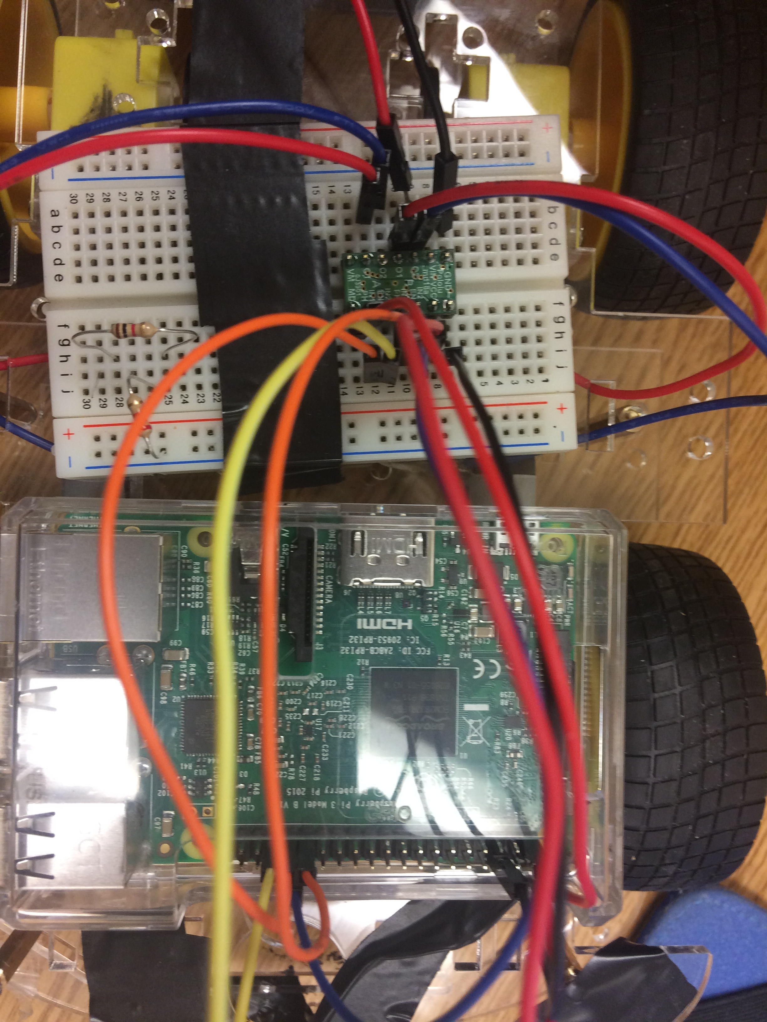
Here are pictures of how everything is connected, and some of the code we’ve used to test our motors:

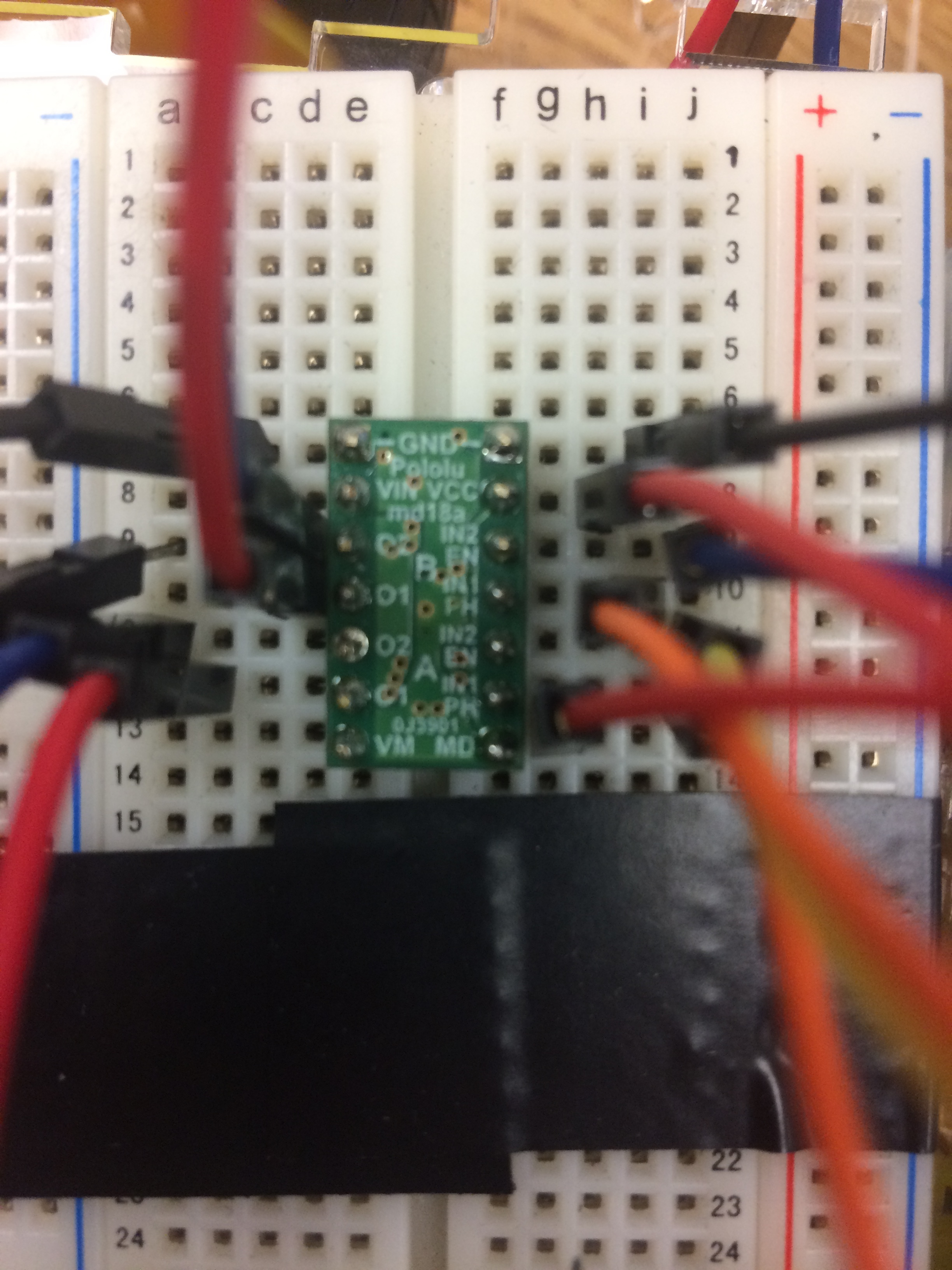
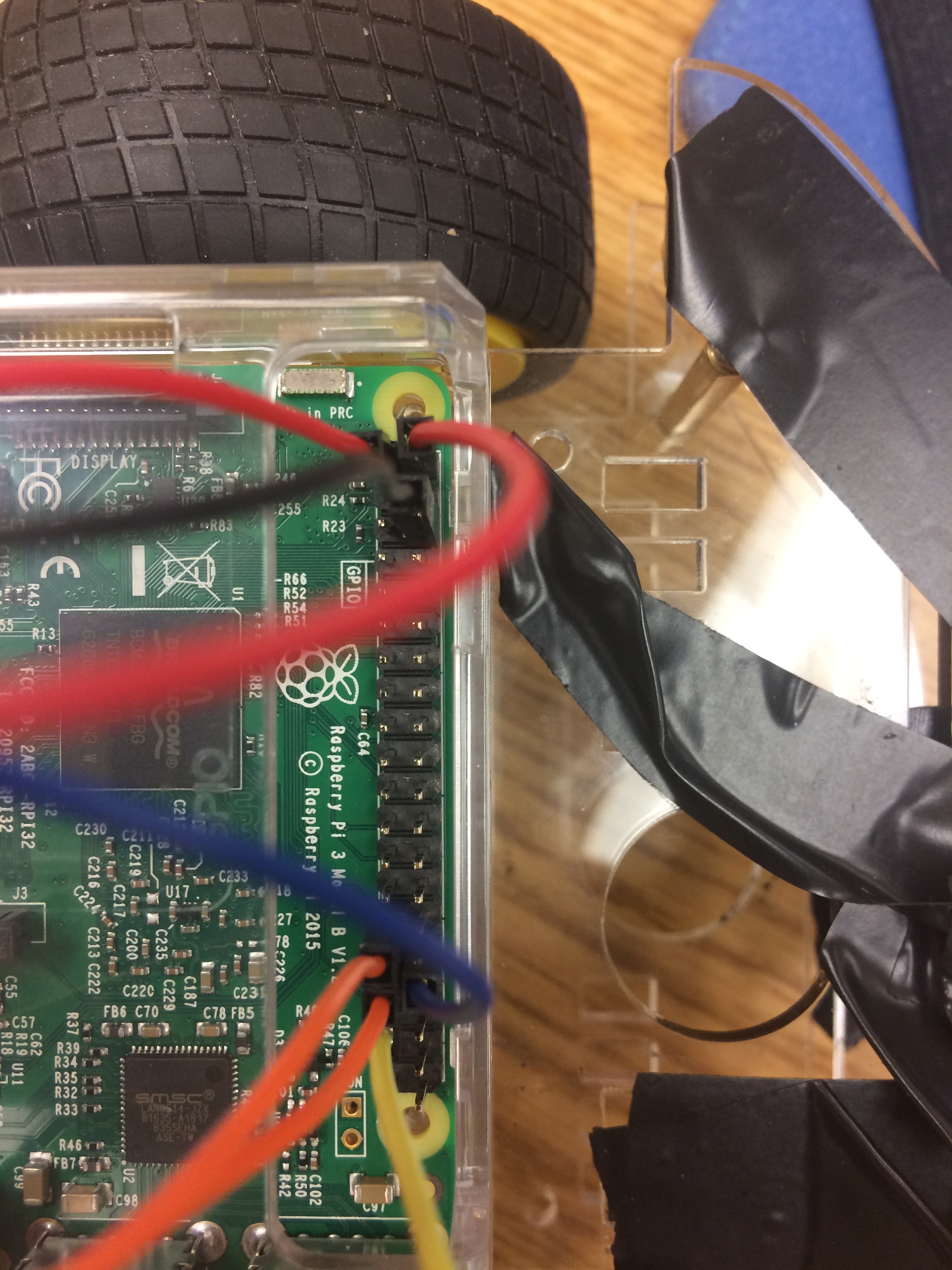
This shows GPIOs 5/6/12/13 connected to PH/EN 1/2, VCC is going to 5v on the Pi, Mode is going to 3.3V on the pi. GND going to pis pin06, which is ground on the pi, both motors are connected to the proper locations, and battery positive and negative leads are connected to Vin/Ground on the DRV 8835.


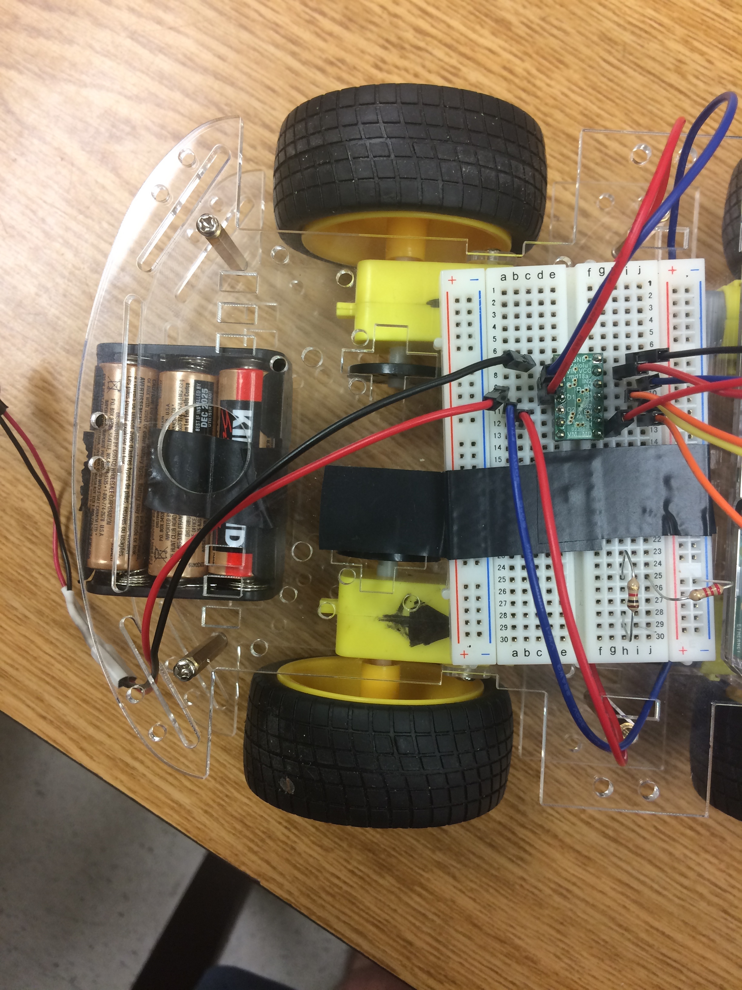
This shows how we have our motors connected together on each side of the car.

Here is the code we are using to test our car:
example.py (2.0 KB)
control_rc.py (899 Bytes)
pololu_drv8835_rpi.py (1.4 KB)

Hello.

I noticed in your second picture that it looks like a male jumper wire is sticking half way out of the breadboard (on the left side, row 9 column a). From your other pictures, it looks like this might be the power from your batteries, but the row of the breadboard it is connected to seems to be one of the motor output pins. Can you confirm this? You might try swapping the connections from the outputs of your driver to your motors (e.g. swap the right motor connections with the left motor connections) to see if the problem follows the motors or stays with the channel on the driver.

Also, you mentioned powering VCC with 5V; since you are using 3.3V signals for the rest of your logic connections, you should power VCC on the driver from 3.3V.

By the way, 4-wheel drive robots like that typically have the motors on each side of the robot wired in parallel (instead of in series like shown in your pictures). Running the motors in series can potentially lead to some problems or odd behavior in cases where the motors are unevenly loaded (e.g. one of the motors stalls). I did not see any specifications for your motors in the link you gave, but when running the motors in parallel, we generally recommend that the driver you are using is capable of handling the combined stall current of your motors.

Brandon

Hi there, thanks for the response.

That male jumper wire is indeed for the battery. We weren’t actively using the battery so I unplugged the positive lead from the motor driver, it looks like it is plugged into a motoroutput, but it isn’t. The picture is misleading.

We have now started using Vcc with 3.3V to match the rest of our system.

I believe the picture is also misleading here, if you look closely you can see a black wire in addition to the white wire that connects our motors together in parallel. After double checking, the motors are connected in parallel.

There is little documentation on these motors, but after some research it appears that they have a stall current of 250mA. And a normal load current of 70mA. Whenever we move the robot forward, we first ramp up the motors slowly to delay the stall current.

We have since removed our two rear motors, and replaced it with a free turning wheel located in the rear-middle area of the chassis. This method so far is working perfectly, except for the fact that with 3 wheels, and the back wheel being free turning, our car struggles to maintain a perfectly straight forward motion. It will stray to the left or right which is problematic. What options do we have here? We can drive four motors, but I’m scared of the motors potentially drawing too much current. This gives us a perfect straight forward drive, but is more risky than using two motors. When we have two free coasting wheels in the back, the car will move straight, but we cannot turn the car because the back coasting wheels provided too much resistance. We can run two wheels and have a free turning differential wheel in the back, but this doesn’t allow the car to drive perfectly straight.

Can you provide any insight into what we could do to:

  1. prevent the motors from drawing too much current (wether weuse 2 or 4 motors)
  2. drive perfectly straight, and be able to turn

Thanks again for the response.

Thank you for making those clarifications. It sounds like you have your robot in working order now; did you switch to one of your extra DRV8835 driver carriers?

The DRV8835 carrier is rated for 1.2A per channel, and it sounds like the combined stall current of your motors (even at the increased voltage) is quite a bit lower than this, so I would not expect the current to be the cause of the damage. It should be fine to run all four motors (two on each channel). The damage might have been caused by that loose battery wire if it made contact with some pins on the breadboard or carrier board. You might consider adding a power switch to your robot to avoid the chance of this happening in the future.

If you want to use two motors and coasting wheels, one option to reduce the influence of a caster wheel is to use something like a ball caster instead. Your robot might still not go in a straight line though, depending on the weight balance of your robot and environmental factors causing different loads on the motors. You might look into using encoders if this is an issue for your application.

Brandon