In addition to answering Jim’s question, what values are you expecting and what values are you getting when you run your code? Can you post specifications or a link to the product page or datasheet for your motor?
- Amanda
In addition to answering Jim’s question, what values are you expecting and what values are you getting when you run your code? Can you post specifications or a link to the product page or datasheet for your motor?
- Amanda
Hello Jim, good morning!
I did not understand your answer, this 1.1V ?? Could you explain?
What could I change in my programming to make the correct measurement on the CS pin?
Thankful!
Marcio
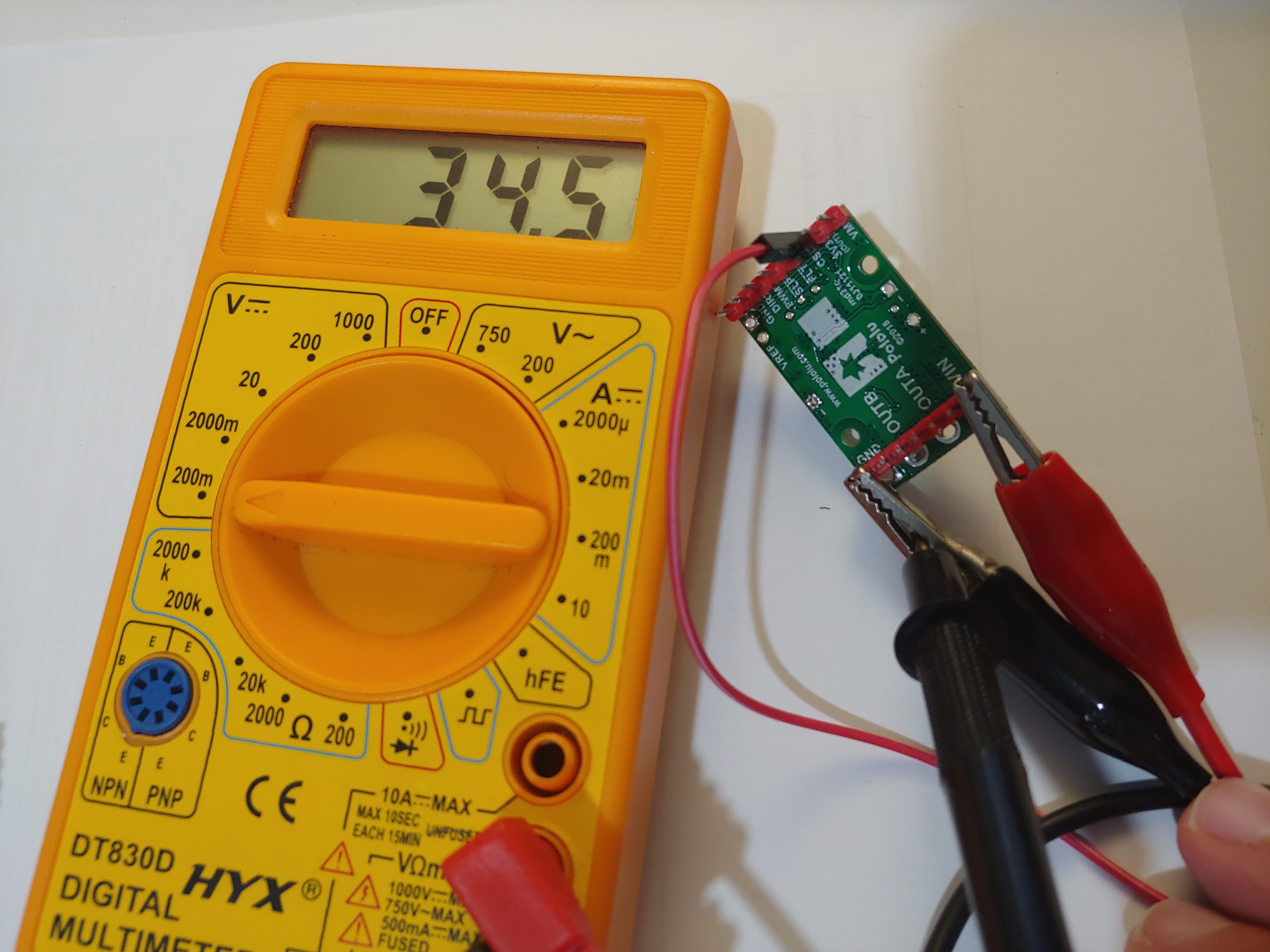
I would just like to get the motor current proportional to voltage across the CS pin. When I execute the code that I sent, the values are not correct. Your pololu site says that when the motor current is zero, we need to have 20mV on the CS pin plus a 50mV offset ??. By doing a basic test I fed the 18v17 driver and measure one voltage at CS pin 34.5mV as you can see in the attached photo. Another question I have: Should I power the driver in (Vin) do I have to get the 20mV in the CS pin independent of any programming?
I have these engines bought in aliexpress:
They are not reliable in terms of quality, I should buy the ones from Pololu.
I am using a DC motor from this seller of 600RPM 12V.
Grateful for the attention!
Marcio
Amanda or Jim,
Will it be necessary to estimate the parameters of my motor??
How to do this to get accurate parameters?
Marcio.
It think you misread the Pololu G2 High-Power Motor Driver 18v17’s product page regarding the current sensor. The output voltage of the CS pin is about 20 mV/A plus a small offset (which is typically about 50 mV). Since it looks like in your test there was nothing connected to the driver’s outputs (so the current was 0A), the reading you are seeing on your multimeter is the offset value for your unit. When you run your code, what values are you getting?
Please note that the current sensor on the G2 HPMD is intended mostly as a rough estimate and is not very accurate at low currents. If you require better accuracy, I recommend adding one of our current sensors to your system.
Can you measure voltage on the CS pin with your motors running at 100% duty cycle under some load and let us know what that is and what your supply current reads?
- Amanda
Hi, Amanda, good morning!
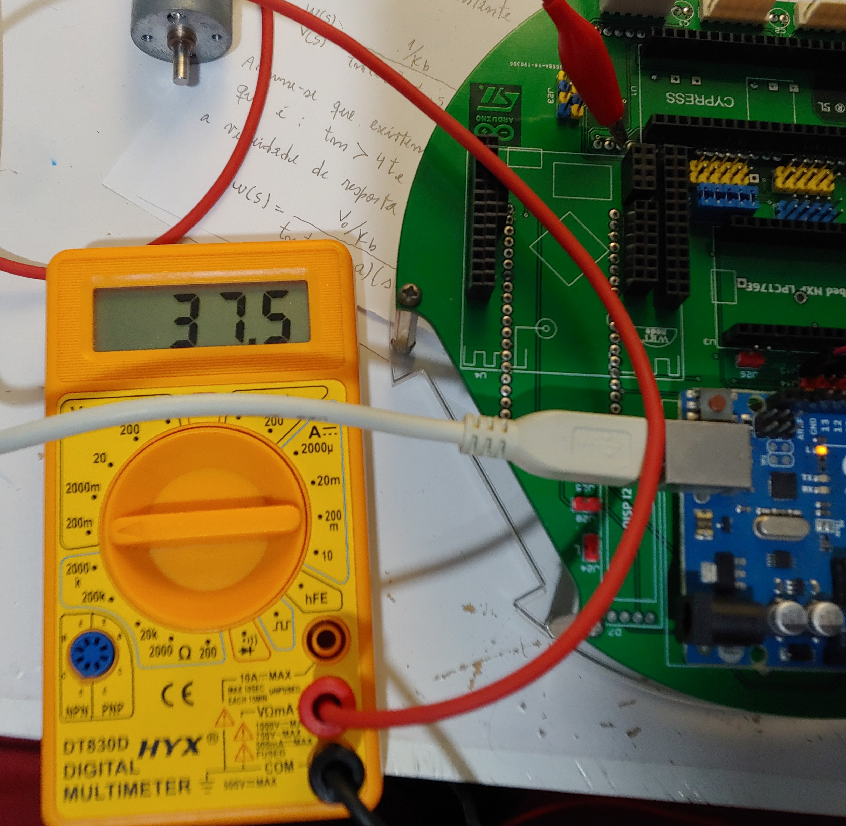
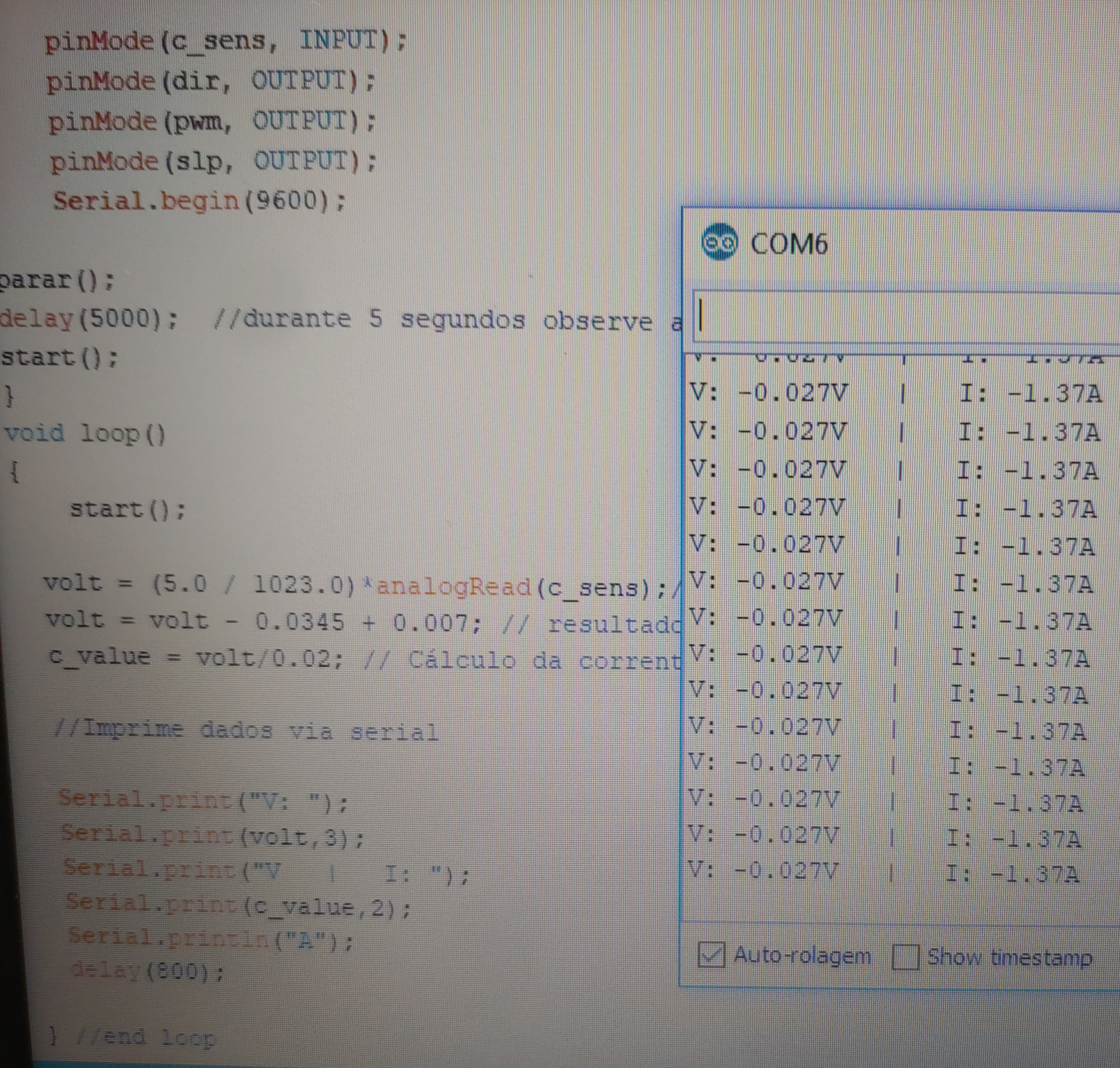
I understood your explanation, I read the current and voltage data through the serial monitor but I still find it strange, see the attached photo.
The code I use is this:
When I run the code, in my power supply the motor current is 190mA, the voltage is 12V (maximum duty cycle) and I am reading 37.5mV on the CS pin measured with a multimeter.
IS THIS CORRECT ??
I do not know how I will include in my code information regarding the document that Jim sent … I have little knowledge in programming to solve. How can you improve, do you have any practical examples so that I can understand this better?
Thank you for your attention!
I’m waiting for your help!
Marcio
code_CSpin.txt (1.0 KB)We do not have any examples for using the CS pin on the G2 HPMD board.
The ADC for an Arduino has a 10-bit resolution, meaning the ADC can only sense 1024 (2^10) discrete analog levels. By default, the analog reference is 5 V on the Arduino Uno, so the resolution between readings is ~4.9 mV per unit. (Jim’s post suggested using the Arduino’s built-in reference, INTERNAL, for measuring voltages 1.1 V and lower (1023 = 1.1V).)
With a current draw of 190 mA and the resolution of the CS pin being 20 mV/A, the CS output would be ~3.8 mV. When you try to read the CS pin, most likely the value returned is 0, since the Arduino’s default voltage reference is unable to detect below 4.9 mV. If you substitute 0 into your code for analogRead(c_sens), c_value equals -1.37, which is what you are getting. As I said in my previous post, the current sensor on the G2 HPMD board is not very accurate at low currents. Also, where did you get the 0.007 value from?
Did you try putting any additional load on the motor to increase the current draw? It does not seem to be the case judging from your first picture. If you did not, can you modify your code to output the values for analogRead(c_sens) before running the program again with your motor under some load? Please let us know the results.
- Amanda
Hello Amanda, good morning!
I understood your explanation well, I’m evolving because of your help, thank you!
The value of 0.007 was the code of the video I sent, when the teacher says that when we have an external connection with a microcontroller we have a small voltage drop and he used this value because he is also using the arduino, but I think it will not change nothing in my code due to your explanation, I will remove it.
I have a question about the 1023.0 I will replace with 1.1V and use the function analogReference (INTERNAL) or I will only use the function in void setup () and I should delete the line of code: volt = (5.0 / 1023.0) * analogRead (c_sens); ???
One thing I did not understand was also when you said that:
“… If you replace 0 in your code with analogRead (c_sens), c_value equals -1.37, which is what you are getting …”
How would the code look?
Do I have to calibrate these measures to improve?
Like I said before, I’m kind of confused by the code.
I’m waiting for your help!
Thankful!
Marcio
Hello Jim, good morning !!
I’m trying to make the calibration where you have it (Calibration example and scaling factor calculation):
http://www.skillbank.co.uk/arduino/calibrate.htm
The author says that:
"I connected the battery to the input and the reading was 2950.
So the voltage would be V = 2950 * 3,275 / 6474 = 1492 mV.
My meter showed it was 1495 mV … "
My values for the scale factor were: V (mV) = 3280/6988 = 0.4693 (I stopped here).
When it says it connected a battery in the input and that the reading was 2950 where it see this value? Did he connect a battery to the A0? Was the battery 2.95V? I did not understand this reading, could you explain?
And the next code is just that:
const float scalefactor = 0.4693; // my scalefactor: yours will be different!
float voltage = sum * scalefactor; // convert to voltage in millivolts
Serial.print (“voltage in mV is:”);
Serial.print (voltage, 0);
I’m waiting for your help !!
Thankful!
Marcio.
I apologize for the confusion; that paragraph is incorrect. I forgot to account for the offset value in the calculations.
Using the Arduino’s built-in reference will give you a better measurement of the CS pin’s voltage output than the default. You would need to change the voltage reference value in volt = (5.0 / 1023.0) * analogRead (c_sens); from 5 V to 1.1 V since the range is from 0 V to 1.1 V and not to 5V.
Yes. Jim has pointed to a good resource on getting a more precise measurement on the Arduino.
I looked at your code again and noticed you are outputting the CS voltage value after subtracting the offset. You should output the CS voltage reading before converting the CS voltage in terms of current:
volt = (5.0 / 1023.0)*analogRead(c_sens);// Read the voltage from sensor
Serial.print("V: ");
Serial.print(volt,3);
Before we continue troubleshooting, please address the questions in the last paragraph of my post:
- Amanda
Hello Amanda,
I still have not put an additional load, the only load is the DC motor of the link that I sent and that has a resistance value of 5.5 OHM’s, do I need to add another load to leave the precise resolution ?? In my photo project I already added the 100K resistor between Vref and GND, would that influence?
How do you imagine this extra load? Do you have any idea?
In the video that I sent the teacher puts a resistor of 12 OHM’s for 10W and the applied voltage is 12V, in this case there is a current circulating of 1A by the resistor … I understand where you want to get … I understood! !!
I’m learning a lot about your answers !!
I’m waiting!
Where did you get 5.5 ohms for your motor? (Did you measure your motor’s resistance directly using an ohmmeter?) According to your motor’s specifications (shown under the “Product Details” tab on the page you linked), the no-load current of your motor is rated 0.2 A, which is close to what you measured in one of your previous posts. So, the current sense output voltage would be roughly (20 mV/A * 0.190 A ) + 34.5 mV offset = 38.5 mV, which is 1 mV off from your multimeter reading of the G2 HPMD’s CS pin. As I mentioned before, the current sense output is not very accurate at low currents and it is not easy to measure small voltages. If getting a precise current reading is important in your project, you should consider using a dedicated current sensor like this one, which has a greater resolution (185 mV/A) than the G2 HPMD’s current sense pin.
As for adding load to your motor, you can do so by adding a wheel to the motor shaft and squeezing it. This will increase the torque and current (since they’re proportional). Alternatively, you could use a power resistor like the one in the video.
Adding an additional resistor between VREF and GND on the G2 HPMD board lowers the current limiting threshold; it does not affect the current sensor’s resolution.
- Amanda
Hello Amanda,
I apologize for the previous post that I said that the resistance was 5.5 Ohm’s, because I gave you information of a motor of 12V, 400RPM and 100mA of current without load, but I did not use this motor yet, it was like this:
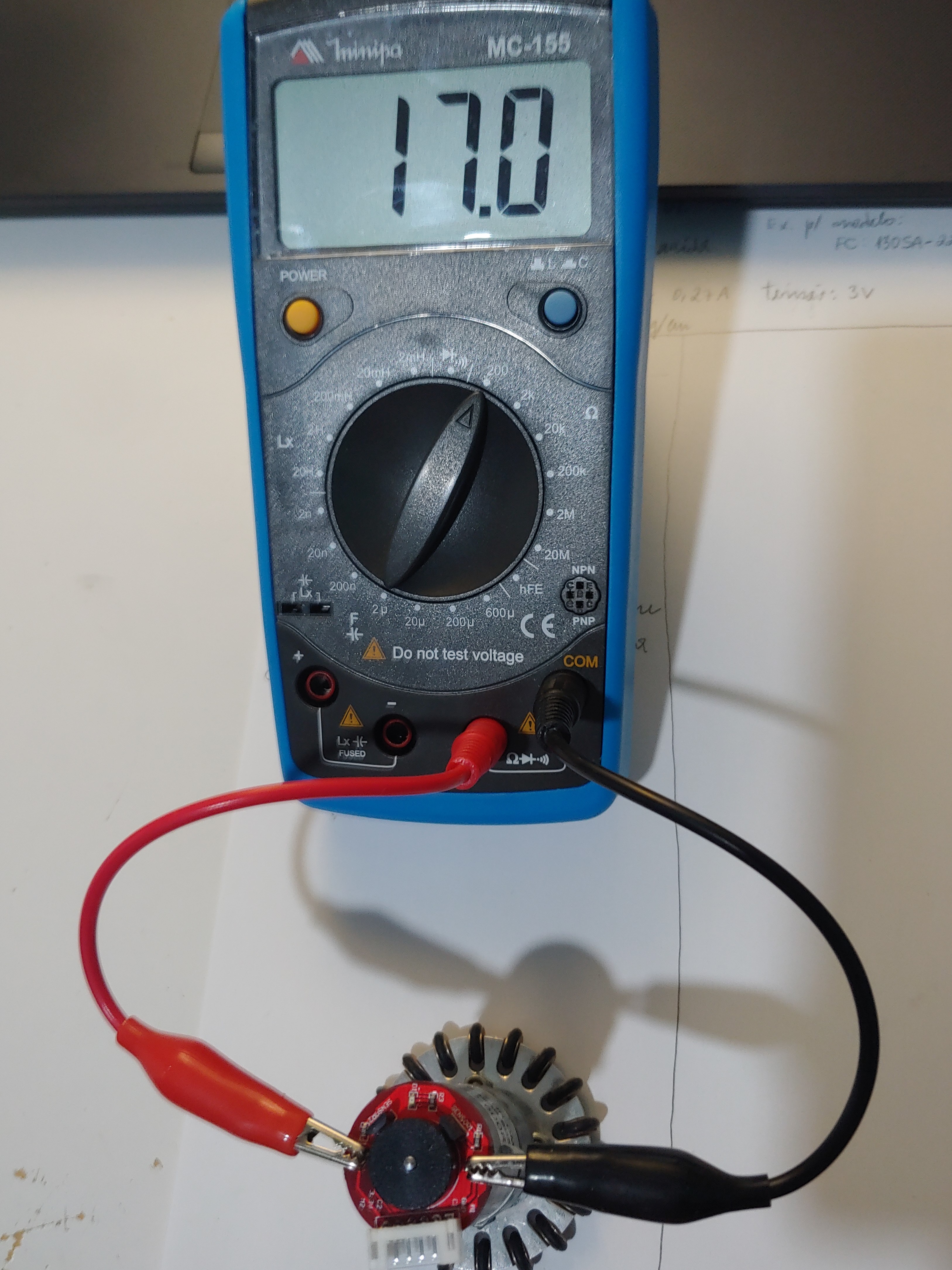
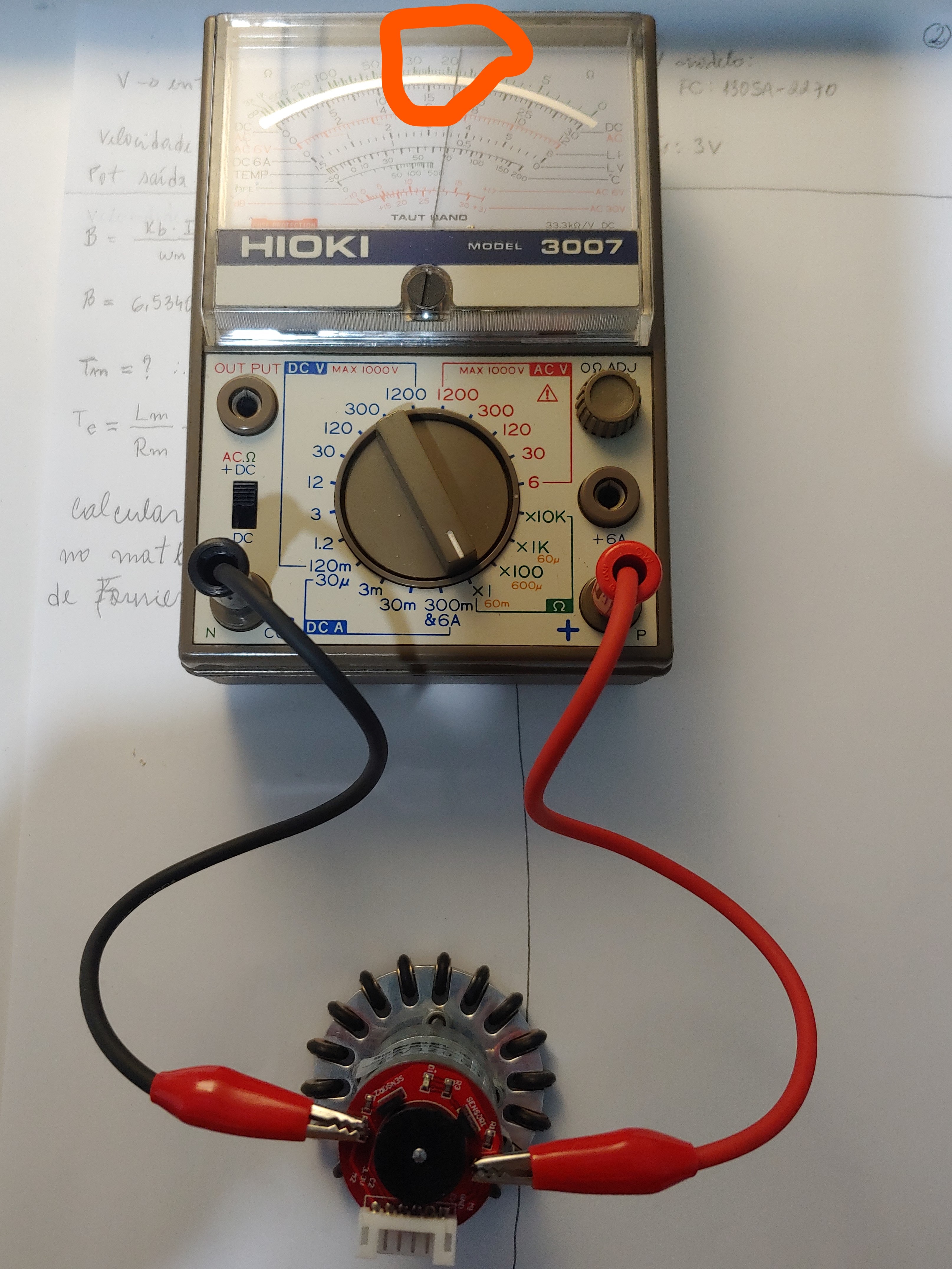
But you can consider my calculations with the motor of 12V, 600RPM and 200mA, I measured the resistance and gave a value of 17 Ohm’s ok! apologies!!
I measured the resistance by placing an LCR and then an analog multimeter for confirmation, estimated the values by blocked rotor, applying voltages from 1V to 6V, then measuring the current by calculating the resistance and averaging these values. Do you have a better way of estimating my DC motor parameters so that I can continue to do everything with higher quality? As a matter of fact this is influencing bad results !! By what method do these processes occur? Most manufacturers do not provide these values (Resistance, Inductance, Mechanical Time Constant, Electrical Time Constant, Coefficient of friction, moment of inertia), as I will need to program the controller . I am sending some photos of these values with two models of these meters and the .pdf I am using to estimate parameters, but I do not know if I should do it this way.
Does the sensor that indicates the ACS714 would be better for my project or using the CS pin gives me to evolve in the code? Because I’m still confused in programming this pin.
I am grateful and I look forward to your help !!
Seaton, Dave - Application Note.pdf (398.3 KB)Before you continue with calibrating your measurements, can you tell me more about your project and what you plan to do with the current readings? How precise does the current reading have to be for your application?
- Amanda
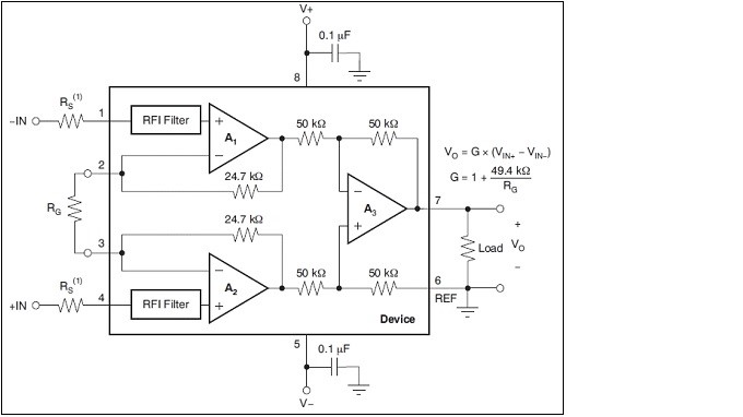
An important circuit for my design is that the current reading of the motor is performed, which is done with the resistance (0.1 OHM) in series with the same force of the motor or the variation of the speed of the wheel, making it capable of overcoming the force of friction, without harming its performance. Since, a voltage on the resistance is a current, the signals to the data that are analyzed by an ADC. Therefore, the INA826 instrumentation amplifier is used. The figure (attached photo) shows the internal circuit diagram of the INA826 amplifier. The gain of this amplifier is a controller of an external resistor, as shown in Eq.
G = 1+ (49.4KOhm / Rg)
By adjusting the gain of the amplifier to 10, the output signal has the resolution of 1 V / 1 A.
Based on this text of work done at my university, I wish I could get the current from my motor proportional to voltage, Amanda understands?
But it does not necessarily have a resolution of 1V / 1A, but I have a reference that with certain current value I have my voltage. I also want to get current and voltage graphs with my HPMD G2 Driver as shown in Figures 2 on page 4 of the attached article.
I’m a little confused in calibration, but I’ll try!
Thankful!
Artigo Jovelino.pdf (1.1 MB)
Hi, marciof14.
Since it sounds like your ultimate goal is to be able to use the motor current measurements to tell when there is extra load (to get a constant torque or speed), it seems like the built-in current sensor on the high-power motor driver might be fine, and you might not need to do any special calibration like Jim posted about.
In a previous post you said with your motor attached that you read 190mA at your supply and 37.5mV on the CS pin. Taking into account the 34.5mV offset you measured earlier, that means the driver was reporting 150mA of current. That seems pretty accurate considering those are pretty low currents and that the power supply is providing power for at least the driver logic as well.
I suspect in that case the output from your code was negative because the current (and therefore CS pin voltage) was so low. The Arduino analog read feature can only read voltages in increments of 4.9mV, and 37.5/4.9 = 7.65, which might be truncated to just 7 ticks out of 1023. That means your code would output (5/1023)*(7) - 0.0345 = 0.0342 - 0.0345 = -0.0003A. You could check for a situation like that by printing the actual analog reading you get before you do anything with it in your code.
That kind of situation is why Amanda has asked a few times for you to try adding a load to increase the current to something closer to 1A. Could you try doing those things and see what output you get from your code and how it compares to the readings from your meter?
-Claire
Hello Claire, good morning!
Yes, I understood your explanation well, as well as Amanda’s. The driver works very well, even if the uncharged motor current fluctuates a bit, the HPMD G2 responds to the calculations. You told me to add load, and I did the following, I held the wheel a little so as not to rotate with the maximum speed and to increase the current, as you asked, when the current reached approximately 0.950A the voltage of the CS pin was approximately 52mV (measured with the multimeter), I’m happy because we know it’s very good, Amanda also said that. And the interesting thing is also when I locked the shaft, the value of the CS pin was the 20mV of the result of my driver … within the expected, because as it has in the datasheet, the values are read, but not with the engine locked.
What I was confused was with the readings with arduino, that made it difficult for me to better understand my HPMD G2.
You asked in the second paragraph for me to do the analog reading before doing something else, I did it:
void loop ()
{
   // c_value = volt / 0.02;
  // volt = volt + 0.0345;
  volt = (5.0 / 1023.0) * (7) - 0.0345 * analogRead (c_sens);
  // Print data via serial
  Serial.print ("V:");
  Serial.print (volt, 3);
  Serial.print ("V | I:");
  Serial.print (c_value, 3);
  Serial.println ("A");
  Serial.print (c_sens, 3);
  Serial.println ("mV");
  delay (800);
} // end loop
I get these values:
V: -0.138V | I: 0.000A
121mV
Is that what you want me to do ??
Thanks again for all, Amanda, Jim and Claire.
I’m waiting for more help!
Marcio
Could you try printing the analog readings before you do any processing of them (i.e. print the value of just analogRead (c_sens))?
-Claire
Hello Clarie,
const int c_sens = A2;
void setup() {
  pinMode(c_sens, INPUT);
  //analogReference(INTERNAL);
  Serial.begin(9600);
}
void loop() {
  Serial.println(analogRead(c_sens),3);
  delay(1000);
}
I print these values in analogRead (c_sens) only with the arduino connected to USB without internal reference:
112101
112010
111211
111112
111020
I print these values in analogRead (c_sens) with the arduino attached to the CS pin and with analogReference (INTERNAL);
120
121
102
100
21
102
I print these values in analogRead (c_sens) with the arduino attached to the CS pin and without analogReference (INTERNAL);
0
2
0
0
1
1
0
Thankful,
I’m waiting!
Marcio
Serial.println(analogRead(c_sens),3);
It looks like you are printing your analog reading in base 3 rather than standard base 10 (for decimal numbers). When using the Arduino println function with integers (rather than floats) the second argument sets the base (not number of decimal points). Please remove that from this test code and try again.
-Claire