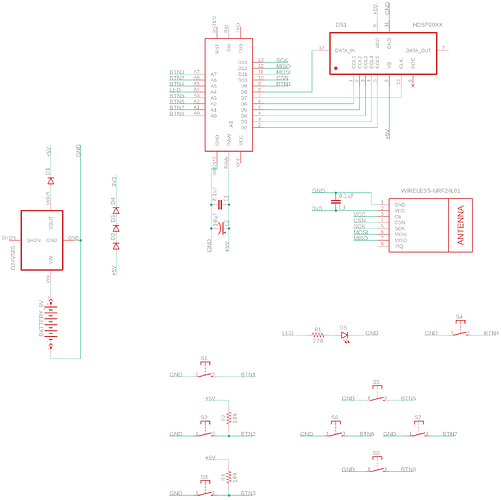
For the past few months, I have been working on a homemade quadrocopter drone. It involves multiple devices, but the relevant ones are a remote control and the drone itself.
Before I add any further technical plans and information, I want to mention that, for one, this is a school project, so I am bound by budget and time considerations and cannot make any significant changes to the setup anymore. And secondly, most of the knowledge about electronics and engineering I have right now I acquired during this very project, that is, I jumped in head first without having a single idea of what I was doing. The result is a big mess in the very roots of the project, and I probably did many things wrong early on. (In hindsight, I should not have chosen this as a school project and rather done it in my free time without restrictions, but alas…)
The remote control includes many components (almost) all of which need 5V. It is intended to be powered by regular 9V blocks. Those 9 volts are fed trough a D24V5F5 to the 5V rail. Another key component is an Arduino Mini. The issue with that is the serial programming pin header, as it includes a connection to the Arduino’s 5V rail, which in turn is directly connected to the 5V rail of the remote control. The result is that connecting to the Arduino through the serial programming header would feed the remote control 5V bypassing the D24V5F5. I only noticed the problem when the Arduino stopped working reliably (supply voltage sagged) and I burned my finger when I touched the regulator, while the remote was powered in this regulator bypass mode. The people over at ##electronics on freenode pointed out to me that the regulator sinks any backfed current, which likely caused it to heat up to such extreme temperatures and fail. I (thought) that I fixed the problem by adding a series schottky diode at the D24V5F5, which should have eliminated the backfeed problem.
For reference, the remote control’s circuit:
(front) https://drive.google.com/open?id=1Eab3IXb3-UHh94SSrp2GZ5yP8ZlEf896
(reverse, mirrored) https://drive.google.com/open?id=1Pf7LgUmI31WVqy4sdKldqFJRtn6zc8Qa
Please note that the images include annotations I made to ask on a different forum about an unrelated issue, and that the Schottky diode is not yet present in them. But it is installed right at the regulator, on the +5V rail.
This was months ago, but unfortunately yesterday I had a very similar problem on the drone itself, which uses a S9V11F5. The drone includes many components, but the relevant ones are a Raspberry Pi Zero, another Arduino Mini and the S9V11F5. The regulator receives power from a 7.4V battery and converts it to 5V. Those 5V are distributed through a common rail to almost all of the electronics. The backfeed issue on the Arduino was solved by physically removing the 5V pin from the serial programming header (so no electrical connection is possible usually). The Raspberry Pi also would receive 5V and feed them to the main power rail any time it is connected to USB, so I ended up using another schottky diode for that.
When the regulator failed, it was receiving about 5.4V from a USB power supply and dropping only 0.4V to feed the circuitry. I noticed that all the LEDs attached to its input power rail significantly dimmed for a few seconds (the voltage sagged, while the PSU is rated for 2A), but they recovered in brightness very quickly and just as suddenly. However, the regulator was so hot when I touched it that I burned another finger. The output voltage increased slightly above 5V (or slightly below the 5.4V input voltage, I cannot say for sure which is the case).
As drawn in this horrible diagram (https://drive.google.com/open?id=1SOUFWAgW6ns-fAl_mobd_yG0HsIcQZoJ), this is how the drone was configured and powered at the time of failure. I suspect that the following are possible causes:
- The circuit was operated for a few dozens of hours at an output current of about 200 - 400 mA and 5.4V input voltage (low drop)
- The Raspberry was powered externally by a source which delivers about 5.1V. This probably resulted in a very tiny leaked backfeed current through the diode.
- The regulator coil’s ferrite coating was slightly damaged, but I tested the regulator under various conditions and it was working without issue. Additionally, it was covered with hot glue for protection.
- I may have applied reverse voltage or significant (a few 100 mA) backfeed current momentarily a few times by plugging in the power supply wires wrong. This happened for fractions of a second, and the last incident was weeks ago, during and the regulator worked flawlessly until yesterday.
Unfortunately, describing everything that may be relevant would be a work of many pages, and while I will have to write a project report, that will not be in English and I cannot afford the time to translate it now. I provided a short summary of what happened and what I suspect may be relevant, but mostly, I am asking for:
- What may have caused such a failure, especially things I did not mention?
- What can I do to make the system more reliable in the future?
- What design errors do I have here, for future projects?
Overall, the regulator worked for a few months before breaking this way. I already replaced it and in fact, I do not need it to work any more than a few additional months. The real problem is that in this development stage, I am powering the drone from a 5.4V source and the failure did not cause much damage, however, that will be replaced by a 7.4V battery later. If the regulator fails then, the electronics would be fried by the high voltage, which means the destruction of the entire project work and a fire hazard from the battery.

