First off, I should mention that I am a novice when it comes to wiring hardware.
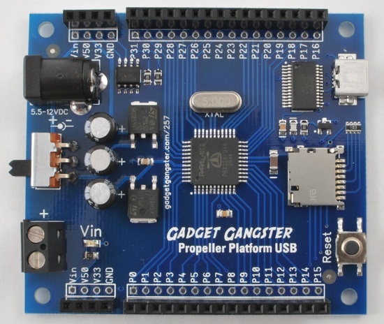
I am trying to connect the MC33926 motor driver carrier to a Propeller platform board (see image below).
Problem: I am unsure of the correct way to wire the MC33926 carrier to the Propeller board. Can someone please advise me?
Additional Details: The goal of my project is to operate a single brushed 12V DC gearbox motor programmatically. I am using the following motor: virtualvillage.com/high-torq … 0-106.html
I am not sure if the motor supports PWM; however, PWM is not crucial for my project. I just need to be able to make the motor move in one direction.
Thank you for posting details and links about your project.
Your motor is a regular DC motor and thus supports PWM. If you just need to make a motor move in one direction at a single speed, you do not even need a motor driver (h-bridge). A single transistor that can handle the current and flyback diode would be sufficient.
If you do decide to use the MC33926, the product page for the MC33926 carrier has a lot of detailed information about how the pins work. Can you try drawing a schematic in a paint program on your computer (you can use the pictures you have as a starting point)? I would be happy to review your picture to make sure your plan is good before you actually start making connections.
You need to connect VDD to the same logic voltage as your microcontroller. In this case, that would be the 3.3V line. Also, you should not pass your motor power through the Propeller board because it is almost certainly not be designed to handle high currents on those pins. Note that the pins and traces for motor power are way bigger on the motor driver than on the Propeller board. I am not too familiar with the Propeller peripherals, but for best performance you’d want to connect IN1 and IN2 to pins that support some kind of hardware timer/PWM.
You should be able to use the same power supply, you just need to split the power with two wires connected at some point where the current carriers are big enough to handle the current. You could use something like our DC Power Adapter Barrel Jack to split the power without cutting your adapter’s cables.
Nope, you would still need to supply a high enough current for the motor separately from the Propeller board.
Why do you need to split the power? My guess is that hooking the adapter into the Vin on the top left of the carrier board will be enough. The Vin on the right carries the power to the Vin of the Propeller board, which should work to power it, unless I’m getting something totally wrong.
If your power supply only has a barrel connector, then you will want something that adapts from barrel to alligators, or wires for soldering.
Either I’m not completely following what you’re suggesting, or you are getting something wrong. Just to be clear, Ryan’s point is that Tony’s diagram shows a situation in which all of the motor current will flow through the Propeller board, and this would probably destroy something. It sounds like you are suggesting powering the motor driver carrier from the small VIN pin on in the upper left, which is also not good, since this pin and its corresponding traces are not designed to carry high current. Motor power should be supplied via the carrier’s large VIN pin on the right side of the board (in Tony’s diagram). One option is to split the power off from this pin and connect it to VIN on the propeller board; another is to connect the small VIN pin on the left side of the motor carrier to the small VIN pin on the Propeller board. Yet another alternative would be to use two separate power supplies, one for the Propeller board and one for the motor driver.
The motor driver power should always be supplied via the large VIN pin. The small VIN pin on the carrier is a convenient place to access VIN and use it to power other low-current components in your system (e.g. the Propeller board).