
Sorry for the confusion.
I carefully stated in previous post that I use the same pin connections CE,CSN for both to eliminate confusion. So, the diagram above did not apply anymore.
"Sometimes the SCK pin is not connected " What that means is, while I was getting the result listed in previous post, I pull the SCK wire and it keeps producing the similar errors.
TSG
You certainly aren’t making this easy.
It is a bad idea not to use the SS pin designated for the processor and failure to do so can, under certain circumstances, cause exactly the problem you are seeing. SS is not an ordinary, arbitrary GPIO pin, and has additional functionality. Read about it in the data sheet.
Jim
With all due respect, I am trying to get this out my way. Any help you can provide since A Star is supposed to be compatible can only make it easier for me to move on. I can only ask for help and hopefully, your team can assist without being frustrated. I am frustrated and need to move on. I have 2 dozen of A-Star that need to be integrated and I can’t seem to do that.
NOTE:
I thought that CE and CSN are user selectable pins. I don’t see PB0 reference on A Star according to the Schematic diagram 32U4 micro although it is on ATmega.
TSG
[quote]I can’t seem to do that.[/quote]That is because you are not doing your homework.
[quote]I thought that CE and CSN are user selectable pins.[/quote]SS is NOT a user selectable pin.
If you want to get this out of the way, do your reading. But since you can’t seem to take a hint, I’ll direct you to the relevant section of the data sheet (p. 128 of the ATmega32U4 data sheet):
[quote]If SS is configured as an input, it must be held high to ensure Master SPI operation. If the SS pin is driven low by peripheral circuitry when the SPI is configured as a Master with the SS pin defined as an input, the SPI system interprets this as another master selecting the SPI as a slave and starting to send data to it. To avoid bus contention, the SPI system takes the following actions:
- The MSTR bit in SPCR is cleared and the SPI system becomes a Slave. As a result of
the SPI becoming a Slave, the MOSI and SCK pins become inputs. - The SPIF Flag in SPSR is set, and if the SPI[/quote]
As a final hint, SS defaults to INPUT and if left unconnected, can be read as either HIGH or LOW.
So, take my advice and try using SS on the A Star as it was intended to be used.
Jim
After reviewing the schematic, I see SS and the rest.
Thank you for your patience.
Can you tell me what are the pin equivalent for CE and CSN.
TSG
You should be able to freely choose which Atmel output pin you connect to CE on the radio.
You must connect SS on the Atmel chip to CSN on the radio.
Both pins must be correctly identified and configured in the NRF24 library.
Jim
You should not try to give hints. CE and CSN are user defined and independent of hardware. I use pins 7=CE 8=CSN or 9=CE & 10=CSN and both produce the same result. The solution was Published by kenno on August 12, 2014 Title: Arduino improving nRF24L01+ reliability
333 void RF24::begin(void)
…
357 //write_register(SETUP_RETR,(B0100 << ARD) | (B1111 << ARC));
358 write_register(SETUP_RETR,(B0101 << ARD) | (B1111 << ARC));
…
509 void RF24::startWrite( const void* buf, uint8_t len )
…
513 // [2014-08-12:SS] blog.surserv.at/nrf24l01_wireless_modules/
514 //delayMicroseconds(150);
515 delayMicroseconds(500);
…
Glad you got it running! Those fixes have nothing to do with the A Star, though.
[quote]CE and CSN are user defined and independent of hardware.[/quote]As I said.
[quote] I use pins 7=CE 8=CSN or 9=CE & 10=CSN and both produce the same result.[/quote]If you are lucky.
Again, SS on an ATmega is NOT a user selectable pin, and failure to keep it high while it is an input will cause the SPI module to malfunction. For this reason, it is safest to connect SS to CSN on the radio.
Good luck!
Jim
I feel that you are toying with me instead of being real helpful. I showed you the code example that I am using and result and you still act like we are in a classroom. I thought the purpose of the forum is to help and collaborate.
Atmega32u4 schematic shows PB0 SS/PTINT0 connected to pin 8. Why don’t you tell me where it is in A Star Micro.
Maybe I am blind. It does not seem to be pin 8 as you suggested.
TSG
Jim
Maybe you don’t realize that I am using A Star32U4 Micro not Mini which clearly show SS etc…
TSG
Jim, TSG,
I’m still in the process of looking over this thread, but I wanted to go ahead and clear up some confusion about the SS pin.
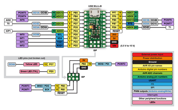
The main purpose of the SS (Slave Select) pin is as an input to allow an SPI slave to be selected. So, as the datasheet says, if the ATmega32U4 is configured as an SPI slave, the SS pin (PB0/Arduino pin 17) is always an input and determines whether the SPI interface on the ATmega32U4 is active.
If the ATmega32U4 is configured as an SPI master, there are two possibilities: the SS pin can be configured as an output or as an input. In the first case, as quoted from the datasheet:
The Arduino SPI library sets SS to be an output, and in this case, the SS pin can be, but is not required to be, used to drive the SS/CS pin of the slave. You can find many Arduino programs that use a pin other than the AVR’s SS pin to control the slave device’s SS/CS. So TSG is correct: the microcontroller pin that the nRF24L01 CSN pin is connected to can be user-defined; as long as the pin specified in the code matches the pin CSN is actually connected to, it should work. (Furthermore, as TSG pointed out, the microcontroller’s hardware SS pin is not exposed on the A-Star 32U4 Micro.)
The text from the datasheet that Jim quoted earlier (“If SS is configured as an input…”) applies only if the SS pin is configured as an input while the ATmega32U4 is configured as a master. The reason for doing this is so that you can make a multi-master SPI bus with a mechanism to avoid contention between different masters.
I will read through this thread again more closely and see if I can suggest anything else toward getting the nRF24L01 working with the A-Star.
- Kevin
[quote]
The text from the datasheet that Jim quoted earlier (“If SS is configured as an input…”) applies only if the SS pin is configured as an input while the ATmega32U4 is configured as a master. The reason for doing this is so that you can make a multi-master SPI bus with a mechanism to avoid contention between different masters.[/quote]
Kevin:
I’m under the impression that the radio is now working for the OP.
If a user chooses to use some other pin to control a device CSN, and happens to leave the designated SS pin unused and unconnected, then on bootup it will be a floating input, with logical value undefined.
This can be disastrous, as a random low on the designated SS pin during during SPI communications disrupts the entire process. Randomly!
This happened to me in a very similar application as the present thread (with an anarduino miniRF) and it took a couple of days to track down.
Therefore, if the designated SS pin is not used for SPI, one should either define it as an output, or tie it high with a pullup resistor (either internal or external).
For that reason I strongly encouraged the OP to discover where the designated SS pin is on the board, and use that particular pin to control CSN on the radio.
I am still not entirely clear on whether the Arduino library handles the SS pin correctly, in the case that it is not used for CSN, and will look into that.
Okay, if everything is working for TSG now, then great. (TSG, please let us know if that is not the case.)
Jim, I agree that it is a bad idea to leave the SS pin as a floating input if you are using the AVR’s SPI module in master mode. However, it is pretty clear that the Arduino SPI library should be setting it to an output when you call SPI.begin() (here is the link to the code again; note the comment directly below that line that specifically talks about avoiding the problem you described). Maybe your application did not use the standard SPI library…?
- Kevin
Kevin and Jim
Gentlemen, the A Star32U4 does not have an SS pin as per diagram on A Star32U4 Micro. That is the issue that I pointed from my last threads. The only reason it works partially is because of the change I made in the library.
ATmega32U4 does but there is no access from A Star32U4 MICRO.
TSG
Kevin:
Yes, the problem I had was with an older Arduino SPI library. I ditched it for a simpler one.
I see that the Arduino library you linked sets a pin named “SS” to output, but I don’t know where or how the symbol SS is defined. Are you sure that SS is defined correctly for the A Star micro? I don’t have a board to test.
tsg:
What do you mean “works partially”? When does it fail and what happens when it fails?
If there is an intermittent problem, it could be due to exactly the situation I’ve been discussing.
The fixes you made are not specific for the 32U4.
Hi
It is not defined at all at the board level.
See this link: a.pololu-files.com/picture/0J528 … 78053aee98
TSG
Jim, Kevin
The transmitter (Arduino Uno) is sending values X=220 and Y=450. After I made the change to the library, The A Star receiver is showing the values but not on the consistent basis as shown below.
no radio available
no radio available
no radio available
no radio available
no radio available
X = 220 Y = 450
X = 220 Y = 450
X = 220 Y = 450
X = 220 Y = 450
X = 220 Y = 450
no radio available
no radio available
no radio available
no radio available
no radio available
no radio available
no radio available
no radio available
no radio available
X = 220 Y = 450
no radio available
no radio available
no radio available
no radio available
no radio available
no radio available
no radio available
etc…
As you can see, the receiver is not consistent. When I use both Arduino UNO for transmit and receive, there is no problem.
The solution was Published by kenno on August 12, 2014 Title: Arduino improving nRF24L01+ reliability
The commented areas are the old stuff. By changing the delayMicroseconds, and the Write_register I was able to get the result above. Before it was all no radio available
333 void RF24::begin(void)
…
357 //write_register(SETUP_RETR,(B0100 << ARD) | (B1111 << ARC));
358 write_register(SETUP_RETR,(B0101 << ARD) | (B1111 << ARC));
…
509 void RF24::startWrite( const void* buf, uint8_t len )
…
513 // [2014-08-12:SS] blog.surserv.at/nrf24l01_wireless_modules/
514 //delayMicroseconds(150);
515 delayMicroseconds(500);
The call to radio.available() reports whether a valid data packet has been received, and the data are ready to be read.
If no data are ready to be read, the program you posted prints “no radio available”. Why?
Most programs just wait in a loop until data are available, then read the data and do something else. Study this example: gammon.com.au/forum/?id=12821
Jim
I just used some examples that were available to test the transceiver. What you are saying make sense. When I use Arduino Uno for both Transmit and Receive, the response was consistent and no errors were found in the data stream. If I keep the CPU busy in a loop, other critical tasks will be affected. The transmitter was sending data (x=220, Y=450) constantly in a loop. If the receiver (A Star32U4 Micro) is not catching some of the data then it becomes an issue. You said before that the changes I made was not the reason it worked, I will say without the change I was getting “No Radio Available” 100% to the point where I thought there was no transmission at all.
TSG