Hi everyone I am new here. I am in an ornithopter project, it involves two servos moving back and forth indepndentley. I need to modifiy their speed and rotation via my computer.
You can command servos individually to any position in their range of motion, and set the rotating speed of individual servos, with any of the Pololu servo controllers.
Normally servos just move at top speed all the time, but the Pololu servo controllers let you reduce the speed of individual servos for slower smooth rotation. It looks like you’re planning on using two different sizes of servo, so you probably want to make sure that they rotate at the same speed and hit the top/bottom of the flapping motion at (or close to) the same time. If one of your servos rotates faster, you can slow it down to bring it closer to the rotational speed of the slowpoke.
The serial servo controllers only generate position commands in response to computer commands. You can configure them for things like controlled speed, center position, etc, but in the end they will only translate position commands from your computer into position control signals sent to the servos. So, with your computer connected you can command your wing-servos to go up and down and up and down and up and down, but once you unplug your computer those servos are going to stay put, not keep flapping.
There are a couple of approaches you could take to disconnect your ornithopter from your computer. First, you could get the Pololu micro serial servo controller instead of the standard serial servo controller. It’s a little smaller and a little lighter (and a little cheaper too) and instead of a big heavy serial cable, you can connect it to your computer’s RS-232 serial port with just two very thin light wires.
If you want a programmable, and completely autonomous (i.e. cordless) servo-flapping robot you’re going to need to either radio control the servos, or use a small programmable microcontroller instead of a serial servo controller. So I guess the next question is what exactly you’re looking to do with this project.
Adam, I didnt mean to unplug the servocontroller from the controller or such… i just mean if I can programm the servos so i dont need to press up and down on the keyboard. I just want to program the movements, click play and let the servos go up and down… it works right? with the standard serial 8-servocontroller. I am not looking into “flying the ornithopter yet” I just want to see and test the movements of the wings
Aah, I see. I was a little confused there. What a computer program makes the servos do is up to you, but you don’t have to do it alone.
There are some programs (both commercial and freeware) you can get that let you create position sequences for Pololu servo controllers from a nice user interface, but they’re all either expensive, or buggy, or both. For example, VSA has a freeware version that lets you loop command sequences, but I don’t think it will let you control the servo speed (and you can’t load or save sequences without upgrading to the pay version). Animaltronicks is a completely free program, which lets you create, save, and load motion sequences, and supports Pololu mode speed control, but I don’t think you can make looping motion sequences with it. Plus it crashes almost all the time.
Personally I think you’re much better writing your own control program. You can use free tools for almost any programming language (are there any that you’re familiar with?) and people on this and other internet forums can help with sample code and debugging. You can even use a simulation/control program like LabView or Matlab (these are quite pricey, but commonly used in schools/industry).
Alternatively, if you just want to get your servos moving, you could pick up something like the Servo City Servo Recorder/Playback Controller. It lets you manually control up to four servos by turning knobs, plus record and playback motions, including looping. The downside is it costs $110, but it might be worth it for you if you want something to get you going quickly.
yeah I know about that controller, very very usefull but costs.
i am going to buy the 8 serial partial kit,
so is the kit complete or does it need any parts?.. it needs soldering only and a serial cable?
so I am going to give it a try and solder it together and download the required software… is there anything i need to think about as I never did something like this,
I spend most of my time calculating and designing modeling testing rc aircraft… this is new to me so i guess I will try the free programs first and see what I can do and later go on and programming myself
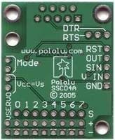
The surface mount components (small chips, resistors, leds, etc) are already soldered on in the kit, but the gold header pins and the serial connector are left off for you to solder on.
Essentially each of the smaller holes (not the four big ones) in this picture has a pin that goes through it that you get to solder on in the kit version. If you have an soldering experience it shouldn’t be too bad. All of the parts you need to solder on come with it, but of course you need your own soldering iron and solder.
Aside from a computer with a hardware serial port and a straight-through (not null-modem) serial cable to connect the servo controller to it, the only other things you need are servos and your power source/sources (batteries, DC power supply, etc) for the servos and the logic supply.
Thank you so much for your help, I have experience with soldering but never soldered any electronics. I suppose I will search a bit how to solder in electronics thank you Adam for styaing up with me, you really helped me:D
I just got the partial today, I have soldered rc wires, metal parts , contacts etc but not electronic chips before, is there any thread or tutorial here or elsewere on how to solder the tiny headerpins into the holes? I am afraid just to overheat the parts… also I heared the one should use 0.7mm to solder wire to solder with, right?
I don’t know of any header-pin specific soldering tutorials, but it shouldn’t be that different from soldering with wire. If you want to practice, you can get a breadboard from Radio Shack to practice on. I don’t think they sell header pins, but an IC chip or an LED isn’t much different. The diameter of the solder isn’t critical, but personally I think the thinner the better, since its easier to control the amount of solder you apply. Again, Radio Shack has some nice stuff called silver bearing solder that works well.
You should be inserting the short ends of the pins from the top side of the board (the side with the components on it) and applying the soldering iron and solder to the bottom side (the side with no components on it), and circuit board material is a good insulator, so there is little chance you’ll damage the electronic components on the board. This doesn’t mean that it’s alright to leave your soldering iron resting on the board for minutes at a time or anything, but your bigger concern should probably be melting the plastic housing holding the header pins together, or overheating the circuit board itself and causing it to begin to “delaminate”. I would say don’t leave the iron on the board for more than 10 seconds at a time, you can always retouch later.
The main technique for soldering header pins it to put solder on just one pin, then make sure that the header strip is straight and pushed through all the way. You can reheat the solder on this one pin as many times as you need to get it to hold the strip perfectly in place, then solder all of the other pins (and maybe touch up the first one a bit). The pins have a little play in the sockets, so you might want to actually plug some servos into the pins first to get them lined up perfectly. I also like to use masking tape to hold through-hole components to the board while I solder them on.
Yeah, a fine-point iron is very handy for applying heat just where you want it.
You don’t need to put any solder on these pins before inserting them in the holes, and actually that might make fitting them in a little harder. It’s great to put solder on wires, especially stranded wire, before trying to solder them together to help transfer the heat between the strands and burn through any oxidation built up on the wires. The pins you’re soldering are solid, so you don’t have to worry about heating the entire pin, plus they have gold plating, which doesn’t oxidize, so solder will wick right up to the surface. The pads on the circuit board you’ll be soldering to are copper, but plated with tin, which the solder should readily wick up against as well.
In general you want to wet your iron with a little solder, touch it to both the header pin and the pad on the side you want to solder, then after a second or so touch your solder to the hot pin/pad, but not directly to the iron (the iron will always be hotter, and it’s easy to just wick more solder up onto the iron and not onto your parts). There’s a good basic description/illustration of how to solder through-hole components in the manual for the previous (all through-hole) version of this servo controller (page 4 of this document). For these header pins you don’t need to bend or trim the ends.
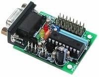
Thank you so much Adam, but my servo controller doesnt have any resistors or capacitors as shown in the manual you linked to, there are actually two manuals for the same servo controller?
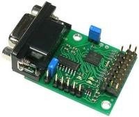
It came as a bag of components and a completely bare circuit board, so assembling it was a little more involved, and the manual included those basic soldering instructions which I thought you would find useful. This old version is no longer made, and what you have is the new version, which comes with all surface-mount components already soldered on.
Since the only components that need to be soldered on this version are the header pins and the serial connector, and these will tolerate much more abuse than electronic components, they dropped the soldering instructions from the updated manual.
I wonder why I cant just connect the board directly to the computer it actually physically fits, why do I need a cable? or is the cable converting something internally ?
If you unscrew the two threaded inserts from the serial connector (just to make it fit) you can absolutely plug this board right into a serial port on your computer.
thanx adam, but I have done everything and nothing seems to work, I soldered everything and checked that there was power, plugged in the mini servo, put the VCC= Vs jumper as it looks like in the picture of the manual and then connected a 6v 2A power source to the servo power… I determened the serial com as com1
downloaded pololuexample and choosed there COM1 but nothing in the board lights up or anything…
so what is it?
should the board light up as fast as I plug it in? I have the jumper on those original two pins VCC= Vs so the power shold reach the board I tried 4.5v as well… it smells like a fried board I feel hmm(not physically smell but)