
Got my 12v12 a week ago. There is a 15a inline fuse running between power and controller. Max current in utility set below 20a. However, somehow the flat copper colored wirer that seems to run to the vin/gnd output has burned a hole in itself severing connection to those outputs. What would likely cause this and what other connections does this affect? Rx input still receives and functions. Bridging the two severed points also resumes function of those outputs.
Are you saying that one of the traces (wires) on the Jrk 12v12’s circuit board is broken? Which trace are you talking about? There is no trace that directly connects VIN to GND. Maybe you should just post a picture of your board.
–David Grayson
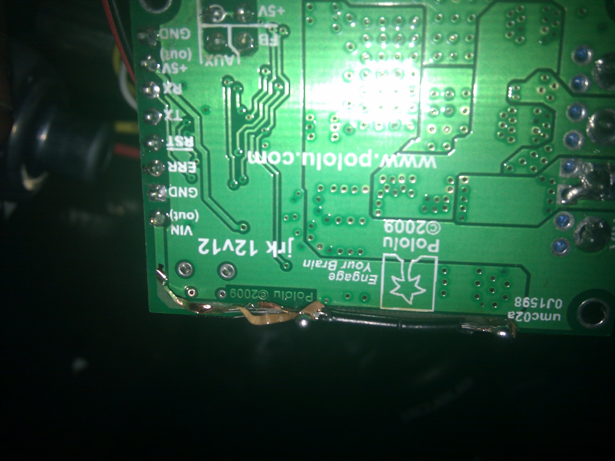
Yeah, the trace runs to vin. U can see in pic I have it bridged with a black wire. The section that burner out is shorter than Tue length of black wire, pic just shows it weird, hut now u see which trace I am speaking of. Thx for help.
1 Like
Oh okay. It looks like something was drawing more current through that trace than it could handle.
Could you please tell me what was connected to the jrk? I’m especially interested in where you connected your motor power supply. Did you connect the power supply to the blue terminal block (on the right side of your picture)? What was connected to the “VIN (out)” pin (on the left side of your picture)?
With regards to your original question, I’ll check our design tomorrow to see if that trace is needed for anything other than the “VIN (out)” pin.
–David Grayson
Yes, my power supply was connected to the blue terminal VIN and GND. It is a 12v power source with a 15A inline fuse between battery and controller. Motor is essentially the same use in a windshield wiper. That motor under my application use should pull on average 8-12A, and will stall at 24A…so should be within reason for the 12v12 controller.
At the time the trace wire blew there was nothing at all connected to the vin(out). On that terminal strip the only things connected were the RX for my 5K POT, and a switch to the RST/GND (which was wired to reset controller when error light causes a latching error when not connected to computer for reset). I discovered the blown trace wire when I attempted to connect a 12V fan to the vin(out) and gnd on left side and it didn’t work…then I flipped over the controller and noticed the popped trace wire. I temp soldered that black wire in place and it began working again…
The biggest confusion on this for me is that the controller is supposed to be able to handle 12A continuous and a peak of 30A…yet with an inline fuse of 15A how would anything possibly pop on the board before that fuse would?
Hello.
The trace you blew out has the sole purpose of providing VIN to the 0.1" header connections; if it melted, you must have drawn a lot of current through it (e.g. by accidentally shorting it out). Since the connection is just there for your convenience, your fix should be fine, and you don’t even have to fix it if you’re not using that pin. You should cut away the trace or glue it down, though, to prevent it from catching on something and tearing or shorting out in the future.
As to your general confusion, the 12A is a rating for the motor driver output; that doesn’t mean you can put 12A through some arbitrary points on the board. Your pickup might be able to carry a thousand pounds, but you shouldn’t be confused if your windshield breaks because you put a thousand pounds on it, right?
- Jan
LOL, nice analogy at the end there Jan ;). Touche. I have burned up a 12v fan, a switch, and now this trace wire in the process of wiring and moving this thing around at different points in time. I am scared to death of burning up the actual controller due to it’s expense…a $5 fan…no big deal…a $100 controller…big deal. So, what likely then would have allowed that type of current to get through the controller and how do I avoid it happening in the future so I don’t burn the actual controller out. Thanks.
This is the first mention of a burned up fan and switch, right? That does make me concerned about what you are doing in general. The trace that burned out should be good for a few amps; how much do you expect the fan to draw? How did it break? How did the switch break?
For general short circuit avoidance, be aware of where exposed contact are, and don’t do things like work with this kind of device on a metal surface, don’t drop screws or tools on it, and so on.
- Jan
Well the fan I think burned out cause I had hooked it up to the motor outputs in a rushed attempt to test something out as I didn’t have my intended motor yet ;). Fan was only rated to handle something like .18A so it quickly fried itself. The switch that burned up I believe was as a result of coming into contact with the metal frame I have attached to the motor. The switch was connected to the ground and RST terminals. However, on the switch end of things there were a few other connection points aside from the two i had used that touch the metal frame while the motor was under load.
You should look into understanding current better (unfortunately, I do not have a resource to recommend–but there are many of them out there). The motor controller won’t force more current into a motor than it wants unless you are applying too high of a voltage.
- Jan