
I’m using 900 mAh NiMH batteries in my 3pi, which can be damaged by overcharging. Rather than take the batteries out for charging (which requires removal of the LCD), I decided to construct a simple constant current charger that can be controlled from the robot. The robot monitors the battery voltage and in the implementation below, turns off the charger when the battery voltage begins to drop after reaching maximum charge (negative delta V).
I first investigated the charge curve as shown below, where the battery voltage was monitored by a digital VOM meter with 0.01 V resolution. It appears that 10 mV resolution is adequate for the purpose (the built in ADC on the 3pi has about 5 mV resolution, using 5V as a reference), but I check for two successive measurements lower than the maximum battery voltage before turning off the charger.
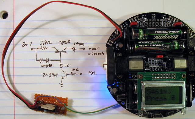
I then designed a very simple constant current source using a PNP power transistor as the current source. The current source works well with input voltage 8-20 volts, although if you go above about 10 volts a heat sink on the PNP transistor is required.
The base current to the PNP transistor is controlled by a 2N3904 transistor, which in turn gets its base drive from PORTD.1 on the 3pi robot. To make the connection simple, I added a two-pin socket next to the battery charge socket, and connected it with a wire to the PD1 pinout in the center of the 3pi board. Hence the three wires from the charger to the 3pi (red=+charger, black=ground, brown=input from PD1). Incidentally, this socket has a ground connection and can be also be used for RS232 output (from TXD) if desired.
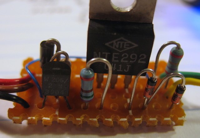
The initial schematic is shown in the backdrop to the first photo below, but it is not at all critical. I assembled the circuit on a piece of perfboard but ended up with a few different parts after raiding the junkbox (last photo).
The output current is given by one diode voltage drop divided by the value of the emitter resistor (0.7V/2.7ohms ~ 0.25 A). The other 1N4148 diode compensates for the base-emitter drop. The charge current can be increased by lowering the emitter resistance (and increasing the size of the heat sink on the output transistor)! The 1N4001 diode on the output is to prevent the battery from discharging through the PNP transistor if the input voltage source is disconnected.
Photos of the assembled board and interconnections
Added 4/3/2009 NPN version of charger circuit. To use this version, change the charge control logic in the code below so that HIGH output on port turns charger OFF.
This circuit has not been constructed and checked!
It was a piece of cake to write the code, given the nice library provided by the Pololu folks!
/*
 * 3pi-battery charger
 * Jim Remington 10/2008
 * began with line-follower example code provided by Pololu
 * https://www.pololu.com/docs/0J21
 * https://www.pololu.com
 * https://forum.pololu.com
 *
 */

// The 3pi include file must be at the beginning of any program that
// uses the Pololu AVR library and 3pi.
#include <pololu/3pi.h>

// This include file allows data to be stored in program space.  The
// ATmega168 has 16k of program space compared to 1k of RAM, so large
// pieces of static data should be stored in program space.
#include <avr/pgmspace.h>

// Introductory messages.  The "PROGMEM" identifier causes the data to
// go into program space.
const char welcome_line1[] PROGMEM = " Battery charger";
const char welcome_line2[] PROGMEM = "3\xf7 Robot";

// A couple of simple tunes, stored in program space.
const char welcome[] PROGMEM = ">g32>>c32";
const char go[] PROGMEM = "L16 cdegreg4";

// Initializes the 3pi, displays a welcome message, calibrates, and
// plays the initial music.
void initialize()
{
	// This must be called at the beginning of 3pi code, to set up the
	// sensors.  We use a value of 2000 for the timeout, which
	// corresponds to 2000*0.4 us = 0.8 ms on our 20 MHz processor.
	pololu_3pi_init(2000);

	// Play welcome music and display a message
	print_from_program_space(welcome_line1);
	lcd_goto_xy(0,1);
	print_from_program_space(welcome_line2);
	play_from_program_space(welcome);
	delay_ms(1000);

	clear();


	// Display battery voltage and wait for button press
	while(!button_is_pressed(BUTTON_B))
	{
		int bat = read_battery_millivolts();

		clear();
		print_long(bat);
		print("mV");
		lcd_goto_xy(0,1);
		print("Press B");

		delay_ms(100);
	}

	// Always wait for the button to be released so that 3pi doesn't
	// start moving until your hand is away from it.
	wait_for_button_release(BUTTON_B);
	delay_ms(1000);
	wait_for_button_release(BUTTON_B);

	clear();
	play_from_program_space(go);
	print("Charging");


}

int main()
{
	int bat, batold=0, count=0;
	DDRD |= (1<<PD1); //PortD.1 is output
	PORTD &= !(1<<PD1);  //charger off

	// set up the 3pi
	initialize();  //wait for button press to start

	PORTD |= (1<<PD1); //turn on charger


	// Display battery voltage and wait for negative delta V
	while(1)
	{
		bat = read_battery_millivolts();

		if(bat>batold) batold=bat;
		if(bat<batold-5) count++;

		if (count>1) break;			//done if 2 successive negative delta V readings

		lcd_goto_xy(0,1);
		print_long(bat);
		print("mV ");
		delay_ms(60000);
	}

	play_from_program_space(go);
	PORTD &= !(1<<PD1);
	clear();
	print("Done");
	while(1)
	{
		bat = read_battery_millivolts();
		lcd_goto_xy(0,1);
		print_long(bat);
		print("mV ");
		delay_ms(1000);
	}
}
It is not particularly practical to reprogram the 3pi for each charge session, but the basic program could be incorporated as a subroutine in a larger program and activated when the battery voltage drops below about 4.5 V. This happens very suddenly! (see the discharge curve below).
The next step? Obviously, when the 3pi is feeling low, he will scurry over to the nearest docking station and charge himself up!
Cheers, Jim
