
Hello,
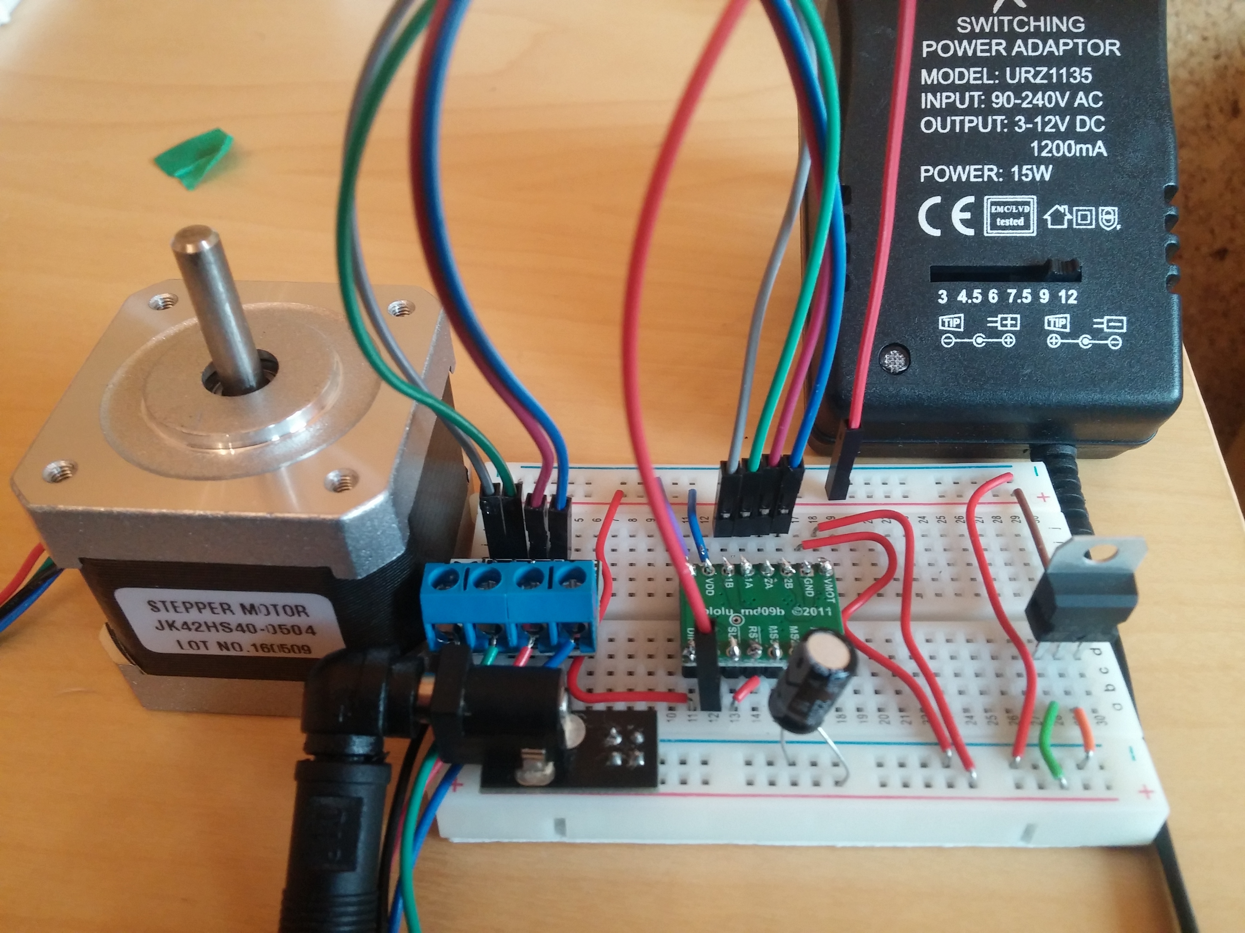
I have an A4988 driver board connected to a JK42HS40-0504 bipolar stepper motor advertised as 12v, 0.4(0.5 in other shop)Amp. Logic input is from a 7405CV. The 12V power for the motor is from switched-mode power supply at 1.2 amps. The board is wired according to minimal wireing diagram. Vref set to 200mV. 200uF capacitor.
When I switch power supply on, stepper motor does one step and stops. Next when I unplug STEP It starts buzzing and after squezzing it it also starts rotating chaotically.
-John
1 Like
Hello, John.
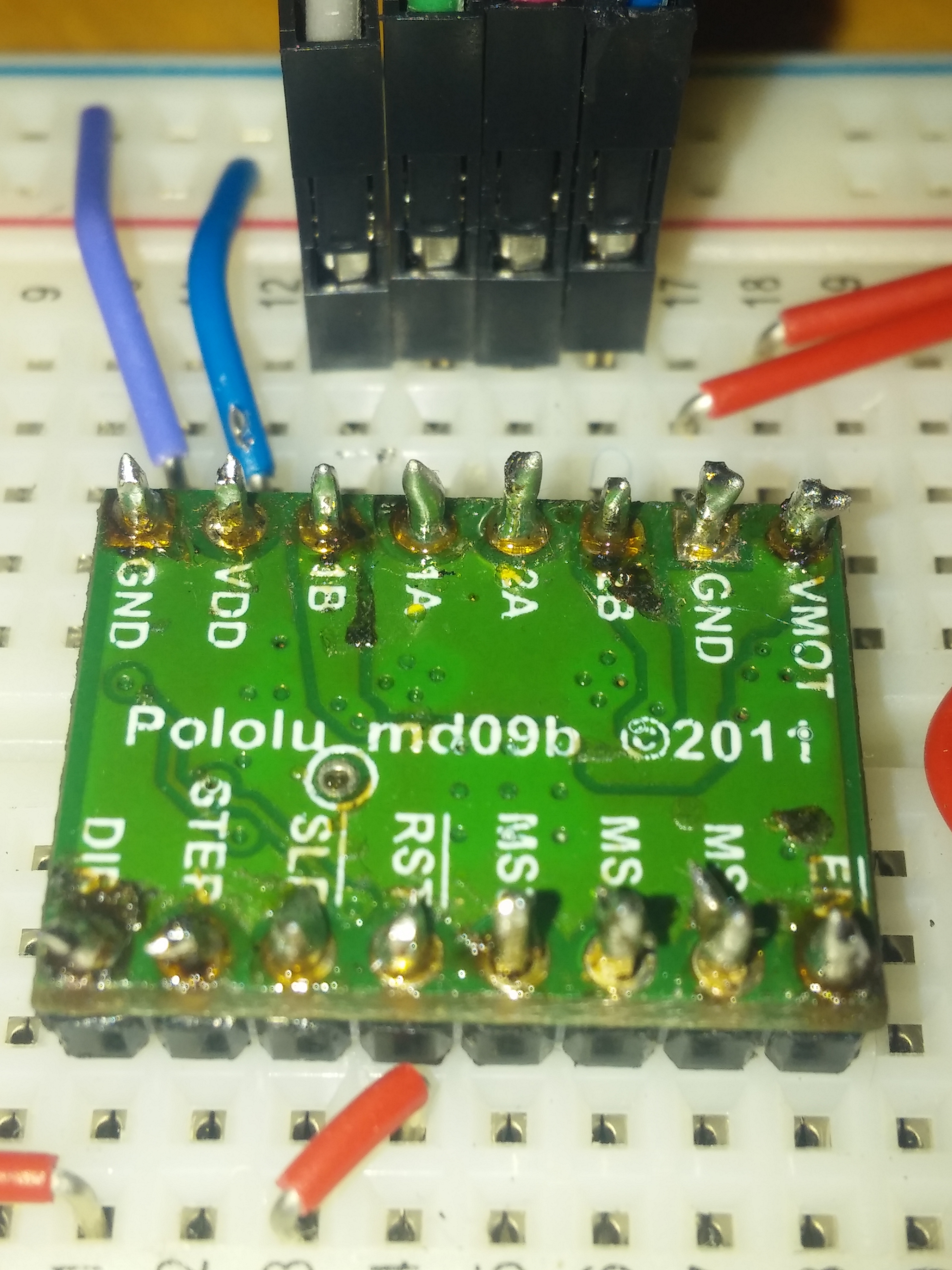
Thank you for posting that picture. Many of your soldered joints do not look like they would make a reliable electrical connection with the PCB. The Adafruit Guide To Excellent Soldering tutorial has examples of good and bad soldering joints in the “Common Soldering Problems” section. Can you try retouching your connections so they look like the good examples in the guide and see if the stepper behaves more like you expect it too? If you are still having problems, could you please post pictures of the retouched solder joints here?
-Nathan
Thank you Nathan for respond.
Problem is still actual.
I noticed weird thing. When I plug long cable only to STEP and leave unplugged from the other side electromagnetic field generates some current in this cable and stepper motor is working(slowly than i expectedbut working) for 10-20sec. Next it stops. When i plug the other end to +5V stepper always stops working
Always when I plug in power supply stepper does one step and stops ( on STEP +5V continious ).
Any sugestions ?
-John
Do I need to set HIGH for at least 1us and LOW for at least 1us every time when i what stepper motor to rotate ?
I thought that when I set +5V continious to STEP stepper motor will be rotating until I change something.
Hello.
The driver will move the stepper one step each time the STEP pin transitions from low (0V) to high (3-5.5V). Also, ~1us is the minimum time the STEP pin needs to be held in the HIGH or LOW state to register, but much slower pulses (like several milliseconds) can work just fine, too. In practice, there is not much reason to use a pulse below 10us.
Many of your soldering joints still do not look like they would make reliable connections. What kind of solder and soldering iron are you using? Did you look through the “Making a good solder joint” section of that Adafruit guide I mentioned? If you look at the picture for the “Heat the joint” step, you will notice that the tip of the iron is in contact with both the solder pad on the PCB and lead of the component going through the board. Heating the pad is important so that the solder flows on to it as well (many of your joints do not appear to have solder on the PCB’s pads). Having the tip of the iron wet with just a little bit of liquid solder before touching the iron to the joint can help the iron transfer heat to the joint.
Also, the amber colored material on your joints is soldering flux and you might try cleaning it off with some isopropyl alcohol and an old toothbrush before attempting to retouch them. After a while, flux can build up like that and make things more difficult.
-Nathan