I have seen the previous post on the A4983 stepper motor driver, but I did not want to be rude and just post to someone elses conversation. My questions are much more basic. I have a stepper motor with the exact same requirements as the previous post, that is, 1.4 amps/coil. However, I am having troubles getting my stepper motor to even respond. I get no response from the board at all. I have gone through the data sheet and have made every effort to set the logic inputs and power inputs according to the datasheet. It has not worked at all. I don’t get any response at all. So, I am missing something here. Can you give me any guidance? Is there a A4983 guide for dummies (because I am a dummy at this point!)? I think I am just missing something small, so any help would be appreciated. I know this is kind of an open ended post, but I don’t even know where to start. Perhaps there are some common mistakes that I am making? Let me know if I am asking the right questions, or if you need more info to respond.
Which carrier are you using? Also, can you post a picture of your setup? One basic thing to start with is your power connections. How are you powering things? Also, what tools do you have available? Do you have a meter? What about an oscilloscope?
If you are using one of our carrier boards, they have a potentiometer for adjusting the current limiting. If the potentiometer is set to a very low current limit, it might appear that the driver is not responding. If you haven’t already, you might try turning the potentiometer while doing everything else correctly.
Well, I thought that the current limiting potentiometer might be an issue. Last night when I was messing with it, I couldn’t find something small enough to turn it. I am using a simple store bought multimeter for measurement. I have nothing fancy. It is all I can afford as a poor college student!! My Stepper motor driver is connected to the Orangutan X2. I am using the digital i/o pins to for logic inputs and the logic supply to the motor driver. I am powering the Orangutan X2 with a 12V DC adapter. The stepper motor driver is being powered with the same 12V DC adapter. Now that I think about it, I probably need to power the stepper motor driver with a separate power supply. Is that right?
Another question I have is, what are the 3V3 and 5V pins for on the A4983? Also, on the REF votlage pin it indicates in the data sheet that it is a maximum of 4V. How would I go about doing analog output in order to obtain less than 5V? I have only been able to read in analog voltages, but not put out analog voltages. That might be a question for another post.
I will not be able to post my setup until later this evening. Thank you for your help. I will post again this evening with more info.
It seems like you might not be following the distinction between the chip and the board that has the chip on it (which is what we have a schematic for–have you looked at it?). The idea with the carrier is that it has both 5V and 3.3V regulators on it, but you still need to connect what you want to use to the board’s logic supply pin. Have you made that connection? If not, that would explain the board not doing anything.
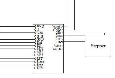
I now understand the difference. I have looked at the schematic. I have a setup up similar to the the attached jpeg. It is not a photo or detailed picture, it is just my lay out. The following pins receive logic input from my Orangutan X2:
DIR
Sleep
RST
MS3
MS2
MS1
EN
The STEP pin is connected to pwm output from the Orangutan X2 so that I may step the motor. The Ref pin is not connected to anything right now. I know that is probably part of my problem. I originally had it connected to +5V, but I read the data sheet and it says to provide 0-4V. I was afraid to connect it after that for fear of messing up something. I have not figured out how to output an analog signal yet. The Vdd pin on the left is provided with 5V which is the logic supply correct? Vmot is connected to a 12V DC power supply. My stepper motor leads are connected in series according to the manufacturers specifications.
I know I am missing some huge chunks of the picture here. First of all, what is the purpose of the voltage regulators? Do I care about the 5V and 3.3V regulated voltages? Also, my power supply is shared by the orangutan X2. Is that okay or is that bad? Thank you so much for your help . You have been very patient with me.
I recommend playing around with the motor driver without the X2 connected at all so you get a feel for how the driver works. You can connect the ones you care about later (for instance, you might not need to have the step size software configurable on the fly, so you could just hard wire the MS pins appropriately).
Connecting the REF pin to 5V might be bad for the driver. That line is connected to a potentiometer that is on the board specifically to allow you to set that voltage (and by extension the current limit).
I don’t know what you mean when you say the leads are connected in series. You should have two coils and therefore two sets of wires; each pair should connect to one of the output pairs. If you’re not sure which wires go together, you can do continuity checks or put a low voltage (e.g. a single 1.5V alkaline or similar cell) across pairs of wires until you feel the motor doing something.
The voltage regulators are there just for convenience; we also have a version of the board that doesn’t have the regulators on board. If you just want to connect this to a microcontroller, for instance, you could power the microcontroller from a regulator on the board. Your connection from the X2 is fine, but you if you want to play with the driver by itself, you can do it with just a power supply, the motor, and some way of making some connections, such as a bread board or some test clips.