this is driving me mad! I had my 1202 with voltage regulator working perfectly on a breadboard but stupidly did not note all the connections before soldering it together on veroboard.
symptomns: only drawing 10mA, I had it working on 1A for my motors previously. Motor ‘hums’ but does not move.
I am contolling steps with a 4060 TTL at 21 Hz - which seems to be working properly and worked on my breadboard.
Here’s my connections in the order on the 1202 unit:
(by ‘open’ I mean not connected to anything)
GND - GND
VDD - 5V jumper
3.3V - open
GND - open
REF - open
!ENABLE - GND
MS1 - VDD (nb I want to 1/16 microstep)
MS2 - VDD
MS2 - VDD
!RESET - VDD
!SLEEP - open
STEP - Open or connected to 21Hz TTL
DIR - OPEN or GND to change direction
Really appreciate any help, I know these are common problems, but its easy to get confused with this.
Just tried lots of other combinations on the conrol pins with no luck. All I get is a whine from the motor but very low current being drawn, no matter how the trim pot is set.
I have two boards soldered to veroboard (yes I cut the strips ok - no shorts there) and both are doing this but they worked on the breadboard.
Either directly or through a resistor should be okay. Can you post a picture of your setup? How are you generating the 21hz step input? Do you have a oscilloscope so you can see what you are doing to the STEP pin?
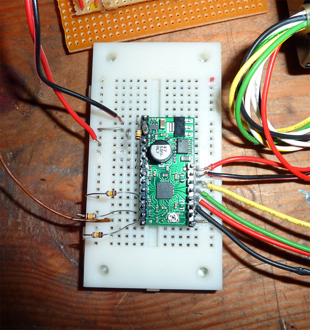
I will post a picture - but it looks a bit of a mess!
I have a frequency meter which is reading 21 Hz, which is what I need.
The main problem is that nothing I do makes the motor draw the current it should (1A) - the circuit just buzzes and takes 10-20 mA. Changin inputs, taking them off, hi / lo, adjusting the pot, nothing - just buzzing motor.
I think the drivers are fried but I have no idea how!
Have you used this motor before at 1A? I notice that it has 8 wires. Do you have it wired as series-bipolar or as parallel-bipolar? Where do the white-color-striped wires go? I can’t see that in your pictures.
When you were rewiring your circuit, did you have power connected? I see a lot of exposed wires in that picture that might have accidentally shorted together.
I’d interested to know the answers to Al’s questions too.
yes I know it looks messy but there are no shorts. I have the motor wired in series as recommended ( as bipolar) and it worked fine previously, it is rated over 1A. The motor coils read the correct resistance (10 ohm). Something must have damaged the circuits when I was soldering them to the boards and wiring them up.
I have now bought two new units. I think the two I have are dead.
Turns out I was using a salvaged bit of wire for the power leads. I noticed a rubber sleeve on the positive wire… turns out it had a damn resistor wired in! No wonder it wasn’t getting any power but the voltage looked ok!!!
Problem solved - all working now, sorry to waste everyones time.