Thank you in advance for your help. I recently received my 24V 5A PS to complete my 3 axis stepper motor (3.06 V 1.7 A) project using 4988 drivers. Unfortunately, 2 of the driver boards have pots that spin without finding stops. I tried to test and calibrate these two, but setting doesn’t hold on either one and where I once saw output voltage on the motor pins, I’m not any longer. Is there a method for fixing the pots on my end to get these up and running correctly?
The third board is fine (was the first one I worked on) and I was able to calibrate and test step the motors successfully.
I am sorry to hear you are having trouble with your A4988 driver carriers. Did these boards ever work for you? What do you mean when you say “the setting doesn’t hold”? How are you doing the current limiting adjustment? Even if the end-stop of the pot stops working, it isn’t necessarily damaged otherwise.
Okay, so now the third 4988 stopped working. No voltage to motor pins and pot misses stops on this one now. The other two arrived that way - this one just started. All I can say is that I’m pretty frustrated! Can someone there please help? Also note that upon closer inspection, there is absolutely no/barely any insulator material at the pots! Shouldn’t there be?!! Happy to send a picture. Please also know this is not damage I created from over-torquing! This how the three 4988s arrived.
We were writing at the same time. Yes, I was able to get voltage at motor pins on both and adjust to .6 using via. However, once calibrated then rechecking later at via produced vastly different results - so calibration not holding.
We test that all our boards are good before we ship them out so, I would be very surprised if you got three bad boards, especially since one was working for a bit. I suspect there is something off with your setup. I would be happy to help you debug it.
Generally, I recommend setting the current limiting using a current meter in line with the motor coil rather than using the vref via. It tends to be more accurate/easier to do. We’d be happy to see pictures! Can you post some closeups of this lack of insulation you are talking about, a picture of the non-functioning endstop, and a picture of the whole setup? A description of all your wiring connections might help us see what is going wrong.
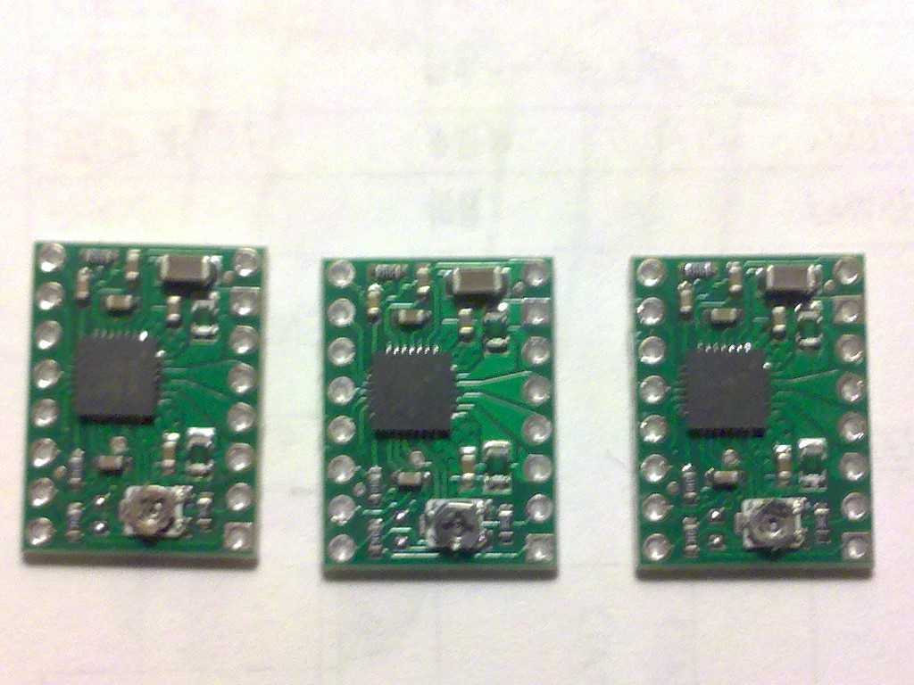
I’ve attached a picture (as best as I could take) showing the boards without the black insulator blocks at the pots. I can see minute traces of the black plastic underneath the screw heads. The one I actually got working the best (before it stopped) has a bit more than the others. Your thoughts? Happy to send pictures of setup next using DMM after I hear back from you. Thank you so much for your time helping me!
The reason the pot might look like it has no insulation is that it is a different potentiometer from the one in the product photo. Your potentiometers look like the ones we have been using in production for some time now. I cannot tell if the stops are okay but the pots all look fine from this picture.
Did you desolder them to take those pictures? Desoldering is much harder than soldering, so I advise avoiding it as much as possible. The chances of breaking a little PCB trace or pad are really high.
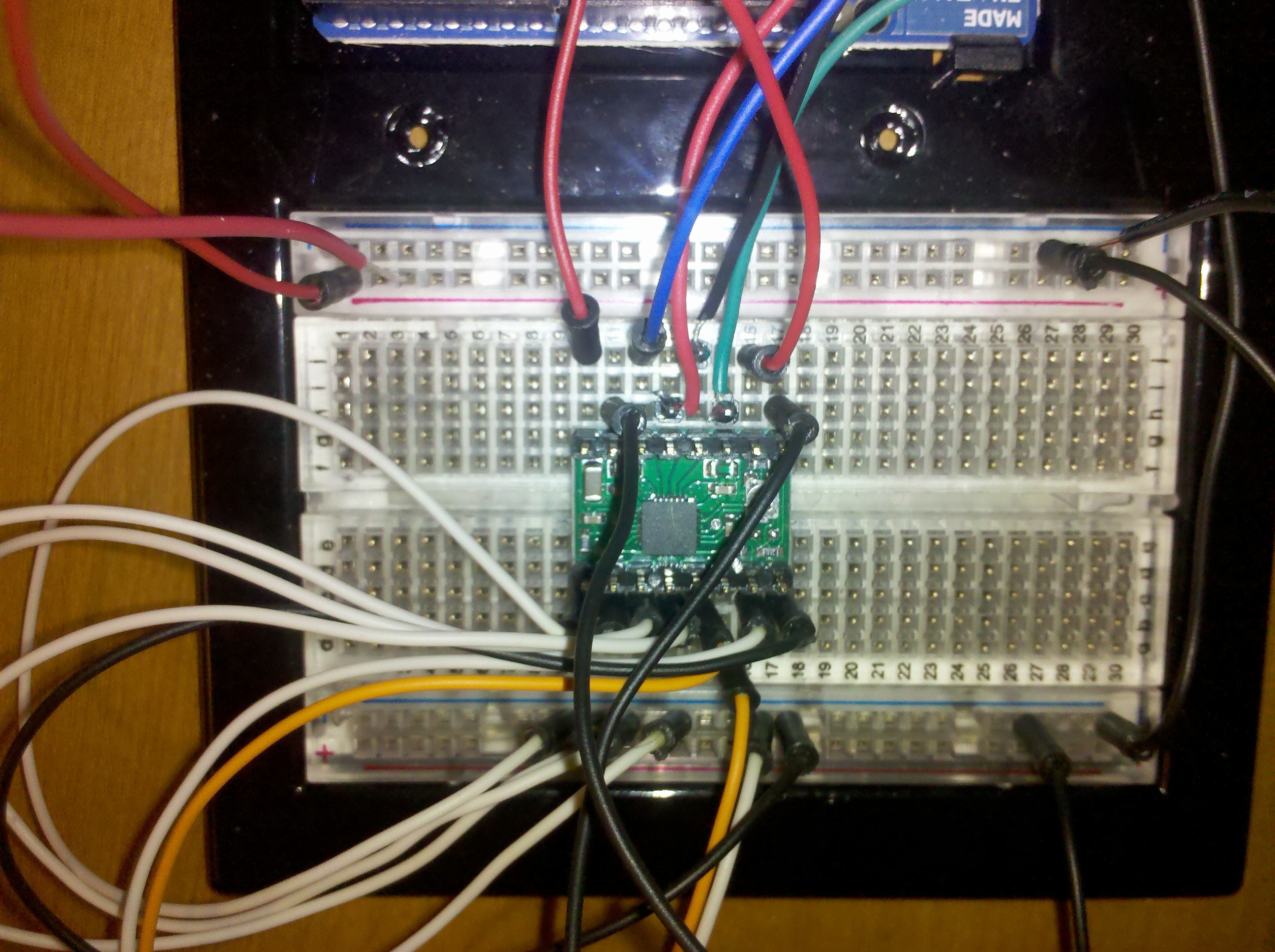
I’m uploading two pics of my setup. Motor wires are blue 2B, red 2B, black 1A, green 1B. Voltage (19.5) at Vmos and 5V at Vdd. I put the DMM in series with the blue motor wire (hopeful to see some current). Nothing. No change turning pot clockwise.
All pins on logic side tied to ground except reset and sleep tied together. Vdd to 5V+ Arduino Uno and ground to logic side gnd rail which goes to Arduino gnd.
I’m using pins with the boards so not soldering/desoldering. The board in the pics is the only where the pot finds stops. No opens or shorts found in circuit.
You cannot use header pins like thumbtacks for PCBs. There is little chance of all of the necessary connections being made. We recommend soldering the short side of the male header pins into the board, and then you can plug the board into the breadboard. It is likely that these connection issues are the source of your problems. but please check your wiring carefully as well.
I’ve never had a problem using the thumbtack approach - always checking for stable continuity and resistance of course. Nevertheless, I did solder the pins and tried them all out again with no luck. All three boards have no voltage output at the motor pins, still (and of course no current).
Under 10x mag, I can see the stops on the two boards that spin crumpled over and underneath the pot screw heads. They are there (or were, I attempted to gently pry one back out but it broke off - ugh). Then my attempt turn the pot on the other one to step up current broke off the pot screw head. Also under mag, I can see a pretty big scratch on the back of the one board that did have a functional pot.
Please understand that I really wanted to order more of these for my class (I’m a STEM teacher) but I haven’t gotten off first base yet. I’m still excited about these little guys though! I know you mentioned all boards are tested before they ship but sometimes the best QC intentions fail. Please advise and thank you very much for hanging in there with me. sf
Can you post a picture of your boards as the are now? Please note also that the pots on these boards are not meant for continual adjustment; they are only meant for setting a default configuration value one or a few times.
No, I’m done. You sent me two defective 4988. Either you’re willing to replace them or not. I can’t afford to waste anymore time on this. The third one I originally thought might have been my fault but now seeing the scratch (which I didn’t put there) - more than likely these boards were pulled from a seconds bin - or perhaps - recycled customer returns. Sorry, not up for anymore run around. I look forward to your reply.
I am sorry you are having a frustrating experience, but please understand that not soldering your pins is a bad practice that very possibly destroyed your boards. This is not some runaround; you can readily look up that disconnecting energized stepper motors is a very common way of destroying drivers. (It’s a bad practice in other, non-stepper-motor applications, too.)
I agree that it is not worthwhile to try to move forward with the drivers you have. If you are interested in giving it another try with new units, you can contact us directly, and we can probably give you a discount on replacements. In case it helps you have more confidence in us or the product, we only accept returns of unopened items, and that has only happened twice for this product. All of the units we sell go through a single consistent process, and each unit is tested before we ship it.