Hi,
I have some trouble with my 30V15A motordriver:
If I connect it to a 12V DC source, I don’t get the desired output voltages. Instead I measure the following:
5V logic voltage is 1,1V
FF1, FF2 1,1V
reset 6V
Only V+ is correctly at 12V as ecpected.
I tried to reset the board with the reset port, but this didn’t solve the problem.
Any suggestions or can I throw it away?
P.S. it worked well for a while - I even don’t know, what I could have done wrong… Current could not have been higher than 2Amps…
That P.S. part is crucial, and it’s certainly not the kind of thing you should consider as an afterthought! If the thing was working fine and then stopped, it certainly doesn’t sound good. Do you have a way of testing the rest of your system? Are the measurements you made with nothing else connected? By the way, if your current is only about 2A, is there a reason you’re using the higher-current version?
Anyway, we can probably at least give you a discount on a replacement, so you shouldn’t throw the bad unit away yet. You should contact us directly with your order info to get an RMA number.
Hi,
after I recognized the failure, I disconnected everything. The voltage measurements I made with only the 12V DC connected.
Do you mean by “testing the rest of the system” the board itself? I already measured some voltages but not having the circuit plan and especially the port information of the controller IC is making this difficult… I assume, that this IC is damaged by whatever.
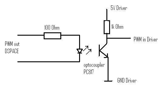
At first I tested the board with a simple µ-Controller (which worked) but I’ve to connect it in the end to a DSPACE autobox with rather expensive hardware. So between the board and the autobox I placed an optopcoupler for each port.
The low current is coming out of a small power supply which will be replaced once I’ve everything working. I just used this as a precaution…
It’s very nice to offer me discount, but I’m from Germany and bought the board from “Brall Software GmbH” (robotikhardware.de).
By “rest of the system”, I meant the parts of your system that are not the motor driver. Is the sequence of events that it worked with the microcontroller, then worked with the bigger system, and then failed, or did it never work after the switch to the bigger system? If the second setup never worked, that would be quite relevant.
Limiting the power input with an output that requires a lot of power is definitely asking for trouble. If that is what you did, you could have been subjecting the motor controller to wild input power fluctuations that could cut in and out of the valid operating range.
I won’t push you much to take the discount, but if you are interested in a replacement, you could email us a copy of your invoice and at least see if the discount is enough to make shipping from the US worth it.
The driver never worked with the “big” system. But I’m pretty sure, I didn’t even connect a motor to the outputs (this cannot be a reason for damage, can it?), I first wanted to measure, if the output is correct.
I’m definetly interested in a replacement, so I will send you a copy of my invoice and refer to this thread?
Is it also possible for you as experts, to figure out the reason of the failure? Worst would be, if the same thing happend again…
It sounds like something in your setup broke the motor driver chip. Can you describe the connections you made to the motor driver? Some ways you could have broken it are by drawing more than a few milli-amps from the 5V out pin, or by applying more than 5 volts to any of the logic-level inputs.
In general, it’s difficult to determine what happened when something breaks. To have any hope, you have to pay close attention and then communicate well. That a part worked for you but then stopped working when you put it in another system is all (potentially) extremely relevant and doesn’t take a long time write. At this point, the possibilities look like some inadvertent thing that happened while you were changing things around (e.g. electrostatic discharge, accidentally connecting things backwards) or some problem in your more complicated circuit in the second system.
Actually that is one possibility. In worst case I could have connected the 5V logic voltage over three 1k resistors in parallel to ground. That would result in a current of about 17mAmps - which seems to be too much?
I think I have to review my optocoupler-board.
Thanks for the tip.
Jan
If the draw on the 5V pin was only 17mA, that should be okay. You probably safely go up to about 25 mA. If you post your optocoupler board’s schematic, we can take a look at it.
What I said about 25 mA in my last post was wrong. The 5V regulator can probably supply around 10 mA. If you need anything more than that, you should use a separate regulator. However, in this case, that probably is not what caused your motor driver to fail.
Hi,
as mentioned in my last post, I created such a connection for every input of the driver and vice versa for the two outputs.
I am not sure, if I already connected FF1 and FF2 but according to your last post, this could have resultet in a too high current (using just 100Ohms in front of the diode)?
That looks like it should be okay for the inputs, but the fault flag lines won’t be able to source current to the LED since they are open drain outputs with pull-up resistors.