I’m using four 18V25 CS drivers in a project. All control lines run to a Xilinx XC9500 CPLD running a VCCIO of 5V. So far everything is working just dandy.
However, I notice when scoping the #RESET line on all of the 18V25s that the line seems to be hovering around 5.6 to 5.7V which worries me vis. the health of the output structures in the CPLD. The board’s 5V regulator is dead-nuts on at 5V.
Is there an explanation for this on the 18V25 or should I be looking elsewhere for the problem? Perhaps a pull-up resistor or … ?
The voltage you are seeing on the [o]RESET[/o] input is normal; it is not regulated to 5 V, and the only thing that matters is that pulling it low resets the board (puts it to sleep). If your drivers are working fine otherwise, I don’t think you have anything to worry about.
Like I mentioned in my OP, my concern is for the CPLD, not the driver. I see 5.7V on the pins driving [o]RESET[/o] on my CPLD. The absolute maximum ratings for the XC9500 input pins is Vcc+0.5V which means the pins driving the [o]RESET[/o] lines are being operated outside the maximum ratings window and I worry my CPLD may be damaged by this.
[o]RESET[/o] is an input to the driver and so I’m not sure I understand how it is that an input is backdriving my CPLD output to illegal voltage levels. Is there a pull-up resistor on the board to a higher voltage (e.g. V+)? If so, which one is it so I can remove it? If not, can you briefly explain how this input to the motor driver is producing 5.7V on my CPLD?
If this can’t be fixed by simply removing a resistor or something, I’d like to know so that on the next revision of the board I can put an intermediate transistor in that line to isolate the CPLD for each channel…
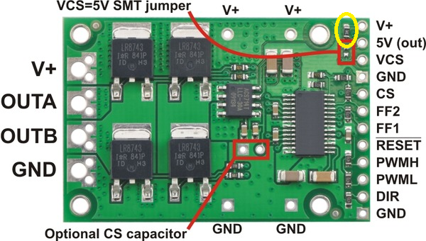
Sorry, I misread your first post. The [o]RESET[/o] line is pulled up to V+ with a 20k resistor, but clamped to 6 V with a Zener diode. (It is not pulled up to VCC because the driver’s 5 V output is disabled when it is in reset.) Because it is such a weak pull-up, it probably should not allow enough current through to damage your CPLD. If you are still worried about it, though, you can remove the pull-up and instead drive [o]RESET[/o] high to allow the driver to operate normally. The resistor is circled in yellow in the attached picture.