Ok, yesterday the controller would move the motors and heat up, at 14amps approx 80deg C and climbing. Today I hooked everything up again but I lowered the PWM down to lowest setting as suggested to reduce heat. I planned on raising the max temp to 125 max hopefully lower but I was going to increment in 5deg steps. I used the USB slider and when I moved the slider I heard a high frequency whine. I took it up to about 25% hoping the whine was due to the low duty cycle and when I did the controller lost communication. I disconnected the power supply,USB,etc and reset the controller. According to the Temp sensor the MOSFET’s never got above 55degC. I tried to go back to all default settings and when I tried it again the blue cap blew the end off and started to spew white smoke. I replaced the cap and now the controller has 0 errors and says it is driving but nothing is happening.
I did want to add one comment, the error code I received before the smoke, said something about failure to communicate with the firmware, It came up twice before the capacitor burned and the Motor Control Sofware lost comm with the controller, I had to reset the sofware and power down the motor controller before it could communicate again.
I would just like to figure out what I did wrong if anything so that I don’t destroy another one of these. A little about my application.
The power supply is 24v from two 12v batteries. This is a Jazzy Jet3 Power Chair.
The control cable that supplies the power and then returns the current the motors is approx 24 inches long. All of the wires are 14g, I tried to use 12 but I could not get them into the holes on the motor controller.
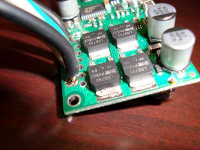
I double-checked the wiring and the cap installation and all matches the schematic.
Do you guys have any troubleshooting tips to check the FETS?
I’m sorry to hear that your controller was damaged. Can you verify that you soldered the capacitor in with the correct polarity? I think it probably would have exploded the first time you applied power if it was backwards, but it can’t hurt to double check. The whine you heard was probably just the PWM frequency, which becomes audible as you lower it. I don’t think this was an indication of a problem.
One immediate problem I see with your setup is that you are using a 24 V battery. While the SMC 18v25’s absolute maximum voltage is 30 V, we do not recommend using supply voltages above 24 V. 24 V batteries can be close to 30 V when fully charged, leaving almost no safety margin for noise/power spikes/regenerative effects from the motor. From the SMC user’s guide:
This becomes even more of a problem when you factor in your relatively long power wires (in that you’re more likely to get spikes over 30 V). For 24 V applications, we recommend our 24v12 or 24v23 versions, which can tolerate spikes up to 40 V.
By the way, have you ever changed the High VIN shutoff setting under the advanced tab of the Simple Motor Control Center? The default value is 25 V, which would probably prevent the controller from driving the motors if your 24 V battery is freshly charged.
Aside from the voltage issues, I also suspect that your motor might just be too much for this controller. If you want to try again with the higher-voltage SMC 24v23, please contact us and we can set you up with a discount, but note that this version cannot deliver as much current as the 18v25, so maybe we should first try a little harder to figure out whether using our SMCs with your motor is even feasible.
I double checked the polarity of the capacitor when it was damaged, it was correct with the positive terminal being on the far right side of the board–assuming the usb is on top–I agree with the fact that it would have exploded on the first run if it had been installed backwards.
The batteries have not been fully charged for a while so the voltage was 25.1, it did raise the VIN limit to 27. When I recived the controllers I called and spoke to someone in tech support–I won’t drop names in public–who told me that anything under 30 volts would be fine.
What is the best method to determine what amperage you need. I looked at the original design of the chair, all of the wires are 14g–I am not sure exactly how many amps 14g is good for, I thought I read about 20amps max-- and they are all quite long. I measured the resistance between the A and B termials of the motor and I get between 2.4 and 4.5 Ohms, I calculated 12 amps @ 24v. I know the stall amperage etc can be much higher, I haven’t even attempted to move the chair the gearbox is in neutral.
Any advice would be appreciated.
Also why would the conroller have lost communication? The error code said that is was unable update the speed or something to that effect.
I think I addressed all of these questions when I spoke to you on the phone, but I want to respond here as well for anyone else who might be following this thread.
I suspect the person you spoke to was trying to confirm that the controller will survive actual operating voltages up to 30 V, but they should have stressed that simply applying a voltage under 30 V is not enough to guarantee that the voltage on VIN will not exceed 30 V as the result of noise, LC voltage spikes, or regenerative braking (the maximum VIN limit is meant to help protect against the latter). We recommend keeping the operating voltage under 24 V to leave an appropriate safety margin, and we recommend not using this controller with nominal battery voltages above 18 V since batteries can have much higher voltages when fully charged.
I generally recommend you choose a motor controller with a continuous rating near or above the stall current of your motor. You can often get by with a less powerful controller as long as you are careful how you use your motors, however (e.g. don’t rapidly accelerate them or change direction and avoid putting them under very heavy load/stalling them for prolonged periods of time). You can approximate the stall current of your motors several ways. The most accurate is to actually stall your motor at a much lower voltage, such as 1 V, and measure the current that it draws. You can then use Ohm’s Law (V=IR) to compute the coil resistance and from that, you can compute the stall current at an arbitrary voltage. You can also use a multimeter to measure the coil resistance, but measuring such small resistances is usually not very accurate.
It sounds like the USB connection was failing while you were dragging the scroll bar for setting the speed. I’m not sure what would cause the connection to fail, but I suspect that some sort of electrical disturbance was triggering a reaction in the computer and causing it to shut off the USB port in various ways (sometimes the high-level drivers are unaware this action has been taken, so the device remains in the device manager, and sometimes the data transfer is cut off while the 5V power remains). This is something that we have observed happening when using the SMCs under heavy load without the included power capacitor installed.