18V15 motor driver appears to be dead


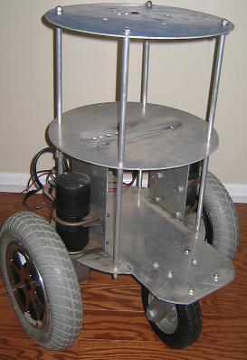
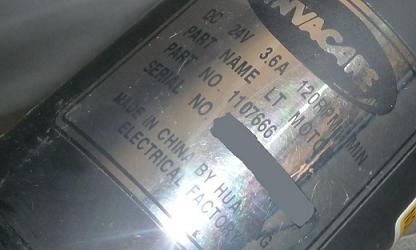
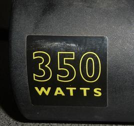
I have been using the 18V15 for over a year with a robot base (not shown) with great success and it’s time to build a bigger robot (see picture). Now, I think that I have killed two 18V15 high-power motor drivers using 3.6 A, 24 volt, 350 W motors from a power wheelchair, which I am operating at 12V from a car battery charged to 12.71 V. See the labels that is attached.


I do not know the stall current on these motors because I am not setup to measure that. My meter only goes up to 20A. I guess I could set up a shunt resistor and measure voltage accross that with my scope, but I don’t know how accurate that will be since I do not have any high power resistors. In fact, stalling these motors is going to be really hard because they are geared down from 3300 RPM to 120 RPM and I would really rather not take the assembly apart. I measure the DC resistance of the motor as 0.3 ohms. This results in a calculated stall of 80 A. Assuming that my measurment is a little high, a 0.15 ohm DC resistance would give us 160A. Now, assume that the stall current is between 100 A and 160A. With the motor running, reversing it would likely give us double (or more) of the stall current.

Here is what I did and what happened. I connected the motor leads and the power. I used a 480 ohm resistor to connect the 5V output to the PWM pin. The motor spins and I can leave it there for quite some time with no real heat generated on the 18V15 board. I can start and stop the motor, sort of pulsing it (not really PWM because I am doing it with my hand really fast; maybe 10 Hz). Then if I reverse the motor by tying the the DIR pin to 5V through another 480 ohm resistor, all works fine and the motor spins in reverse.

With this setup, the 480 ohm resistor connected to the DIR pin lost contact and everything stopped. I have not been able to restart the driver. I disconnected and reconnected power, tied the reset high, and let it cool off (even though it was not hot). I took off everything, reapplied power, measured the 5V output and it is in the millivolt range (between 10 and 20). So the 5 volt regulator is not coming on and providing an external 5V to this pin does not help. None of the FETs are shorted and their gates are not shorted to ground.

O.K. so I figured that the 18V15 driver chip is dead and I proceed to the other side. This is another new 18V15 and a different motor. I ended up doing the same thing to this one, but this time the DIR pin was on a toggle switch, which provides a very small delay, and I intentionally flipped the switch (ensuring that I was not shorting something out). This killed this 18V15 (I know… but I didn’t do it a third time).

So this was a long description leading up to the question. Is there a specific amount of time required before the motor can be reversed? I would like to use the motors to provide a balancing effect and I may need to rapidly reverse them. By the way, this works with motors that are 12V, 1.75 A, 60 W stall because that is what is on my other robot and this is how I use them (although the mass that is moving is much smaller, making the momentum much lower). Any suggestions for a motor controller that would work for this? I can probably spend about $200-250, but I really do not want to spend $400 or $500 dollars though.

Hello.

If you are not getting the 5V out with no load on it, the driver probably is destroyed. The drivers can handle the direction input being changed at several kHz, so the rate at which you were doing it by itself should not have been the problem. However, depending on what the motor was doing and what your power supply is, that switching might have caused voltage spikes large enough to damage something. Did you have the through-hole capacitor mounted? What is your power supply, and how is it wired to your board? Separately, I don’t know if the 10Hz is an overestimate, but that’s pretty fast, so if you were furiously trying to move a wire around, is it possible you occasionally made contact with something else (and shorted something out)? For the unit with the switch, can you provide more details about what happened? Was the motor turning one way, and then you flipped the switch, and it just stopped rather than changing direction? Did the setup ever work for switching direction?

We have some new motor controllers coming out soon that might simplify things for you. Performance-wise, they’ll be about like the higher-power version of the driver you have, but they will also have a microcontroller so you don’t have to generate the low-level control signals yourself.

- Jan

The through hole capacitor provided with the board is soldered in. The terminal blocks provided are also soldered in. The 0.1 spaced male header has the GND, DIR, PWM and 5V soldered in. The power supply is a 12 V Duralast 24F-DL car battery (a rather large one as car batteries go, with 600 cold cranking amps). I have a set of wires that has a fuse in line and clips on one end that fit the battery terminals. This wire was attached to individual wires that were stripped to about 1/8" and screwed into the terminal block power and ground. The motor wires were stripped to about 1/8" and screwed into the terminal block motor terminals. I attached an 8" wire to the PWM terminal. This wire has a female header on one end, is stripped to about 0.25 inch on the other side and has a 470 ohm resistor soldered to this stripped portion. The other lead of the resistor is free to push into a breadboard or whatever. I attached a similar wire to the DIR terminal. The 5V terminal just had a similar wire without the resistor.

On the first motor controller, I was touching the resistor lead of the wire attached to PWM terminal to the the wire attached to the 5V. The motor ran during that time. With the motor stopped, I held the DIR resistor lead and 5V together and I touched the resistor lead of the wire attached to the PWM terminal to the other two. The motor ran in the other direction at that time. Then while holding the three together, the DIR resistor lead Islipped out of my fingers and lost contact. I do not think that it touched anything else, but I can not be certain. That is when that motor controller failed.

On the second motor controller, I put the free resistor leads and the wire attached to the 5V into a breadboard. I have a switch on which two wires are soldered and I put one wire onto the breadboard with the 5V and the other onto the breadboard with the DIR. I turn on power and jumpered the breadboard from the 5V to the PWM so that the motor would turn on. The motor was running and then I flipped the switch, thereby attaching the DIR to 5V through the 480 ohm resistor. The motor stopped and the motor driver was dead. I never tried running this motor driver in reverse except when it failed.

I am glad that you have new models coming out soon. However, my need is a little more immediate.

Hello.

We plan on having the new motor controllers available in the next few days; would this be soon enough for you?

- Ben

Sorry, after my last reply I ordered the Dual 25A Roboclaw from Basic Micro through RobotShop. This unit is a bit costly ($125), but it offers over current protection and claims to allow instantaneous reversing capability. It also claims to be regenerative. It also has inputs for quadrature encoders (which I also ordered today).

We’ll probably be distributing that controller soon, so we’d be interested to hear about your experience with it.

- Ben

I like the Roboclaw 2 channel 25A motor controller. It works better than I anticipated and has quite a few options for control (including closed loop options).

I am currently using a Hitec transmitter and receiver (model airplane remote control) to control the motors through the PWM inputs on the Roboclaw. I am a PhD student and my research deals primarily with sensors (LIDAR, cameras, GPS, etc.) on a mobile robot. I am focusing on data collection and I am able to do this data collection while controlling the robot manually with the wireless remote.

I have caused the Roboclaw to go into a ‘limp’ mode. After running it at full power for about 10 or 15 minutes, maneuvering the robot like a remote control car. In this mode, the power was reduced in such a way that the robot seemed to be moving in slow motion (maybe 25 to 50% of full speed). Upon pressing the reset button, the controller restored full power.

Next year (likely in the summer months) I will change to an autonomous mode with a serial communications link controlling the robot with an embedded system or computer. At that time I will also begin to use the motor shaft encoders. I will not be writing code for this part of the project until that time. Also, I hope to utilize ROS (see willowgarage.com) for the navigation and path planning.