I have the 12v12 and am contemplating an option to supply higher current to my motor in one direction while maintaining the feedback control.
I am able to power the motor fine in both directions with the controller, however I am lacking sufficient power and running into stall situations on the “push” side of my drive. My gadget is designed to drive a lever back and forth. The “push” function requires far more effort to accomplish than the “pull”.
The motor I am using to drive the lever should have sufficient power to handle both sides of this operation, however after reviewing the specs I believe that my snag comes in the current limits of the controller.
Is there a way to bypass the controller for the motor power on the “push” side thereby allowing me to use higher levels of current (approximately 35-45A), but still maintain the ability to revert back to the controller for motor power and feedback on the “pull” stroke?
The 12v12 is the only controller I have found that works easily and perfectly for my non electronic building/coding brain. I need and enjoy the ability it gives me to easily control the placement of the lever on the “pull” stroke based upon the position of the slide pot that I use to control it. However, I only really need this position control on the “pull” stroke. The “push” stroke position is not important as simply powering it till full extension would be sufficient every time. I just clearly need more power to consistently get that full “push”
I hope my inquiry is clear enough to understand. If not please let me know where more clarification is needed. I really want this 12v12 to be my solution. Your assistance is greatly appreciated. Thanks.
You could use a DPDT switch to switch between having the motor connected to the jrk and having it connected directly to your high-current power supply. Be sure to get a switch that can handle all the current you will be putting through it. I searched Google for “dpdt 50a” and found this part, which would probably work for you: parts.digikey.com/1/parts/980869 … -s732.html
If your system can damage itself by pushing too hard against its mechanical limits, then you could put a normally-closed limit switch between the DPDT and the high-current power source and arrange it so that it gets pushed before the motor damages your system.
You can also set a duty cycle limit on the jrk to prevent it from driving in one direction, or at least prevent it from driving too hard.
Also, how are you powering things? Are you sure that your power supply can handle the push stroke?
Thanks so much for the help and ideas. You guys are great! Thats why I have continued to use your services…as customer service is top notch =).
So if I get this correctly, that switch you attached, being an “ON-ON” switch will be allowing power to one or the other at all times right? If thats the case then I could probably rig up my slide pot to activate that switch at one end of the slide thereby activating the high current switch right? Then by moving the slide pot back the other way would automatically switch power back to the 12v12 right?
I hadn’t thought about the limit switch option either…certainly wouldn’t hurt. Thanks for that idea also =).
As far as the duty limit are you saying then that I should set that up to basically not drive the motor at all on the “push” stroke since the motor runs outside the 12v12 on that part of stroke?
I guess the biggest question in all this is whether the feedback (sensor is a string pot) would get confused or still work properly since I’m going around the 12v12 for the “push”, but I would imagine it should still run properly since the string pot still moves. Just wanted to make sure 12v12 wouldn’t somehow try to fight things with the outside powering occurring on half the stroke.
As for the power supply, yes I’m sure the power supply can handle the current just fine and dandy =).
Look forward to your follow-up response. Sorry for the lengthy posts. Have a great day!
No. The datasheet available on Digikey.com shows that the switch has a center position where none of the terminals are connected.
What kind of rigging are you talking about? Maybe a mechanical link of some sort could do what you want, but I was thinking that your machine would just have two separate controls, a slide pot and a DPDT switch.
No. The configuration settings of the jrk do not matter during the push stroke because it would be completely disconnected from the motor. But you might want to set a one-directional duty cycle limit on the jrk to prevent it from damaging itself. Prevent the jrk from trying to perform the push stroke while it is connected to the motor.
During the push stroke when the jrk is disconnected, the jrk will detect that Scaled Feedback is not equal to Target so it will try in vain to move the motor by turning on its motor output MOSFETs. This is OK. Those MOSFETs won’t do anything because the motor will be disconnected from the jrk.
The reason I didn’t want to use a DPDT as a completely separate switch is that I am trying to keep the whole system operable “seemingly” by one slide pot as separate switches will interfere with the smooth push/pull operation.
If I were to setup a spst momentary on toggle that was activated “on” once the slide pot is moved to the full “push” position would this work? Running power through the 12v12, the motor seems to stall out part way through the push (my theory being likely due to needing more current to power through the rest). So, I figured if I connect this spst switch directly from the motor to the power source, bypassing the 12v12, will this work? My thought is, since the slide pot is moved to full “push”, once the resistance decreases from the added push delivered directly from the power source that it won’t hurt anything for the 12v12 to continue to power on the stroke as well…
Does this make electronic sense or am I missing something in the seeming simplicity of it in my head?
I think you need to DPDT to bypass the motor controller. The current that flows in to the motor from the power source must flow out of the motor’s other lead and get to GND. That current is too high to go through an output of the jrk 12v12, which seems to be what you are proposing.
Also, when your SPST switch is closed, it sounds like one of the jrk 12v12’s outputs will be connected directly to your power supply. That can easily cause a short that would damage the jrk.
If I’ve misunderstood you, please try describing your circuit diagram better.
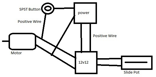
I have drawn up a quick crude sketch so hopefully it explains it a bit better. As you should be able to see from the sketch the SPST switch connects an independent positive cable from the power source (there is also a separate ground as well). This should keep the whole operation of the high current load separate from the 12v12 or still would cause current to pass through?
Any insight into this and whether it should work or possibly a different approach to allow seamless operation of slide pot while activating/deactivating a DPDT switch would be great.
This is all for a prototype concept I am working on. If it works I would preferably want to then see if you are able to produce mass numbers of a higher current controller with feedback like the 12v12.
The schematic you have drawn above is totally wrong and will basically guarantee desctruction of the jrk. In your drawing you have shorted one of the jrk’s motor outputs to GND, which guarantees that when it tries to move the motor in the “pull” direction there will be a short circuit. You are causing a similar short on the jrk’s other motor output whenever the button is pressed. The potentiometer needs to be connected to the jrk with three wires.
I recommend that you use the DPDT switch that I recommended above. If you’re not sure how to wire it, post a schematic here and I can check it.
My error on the POT display on the schematic. It is of course connected with 3 wires, i just neglected to include three in drawing.
I see what you mean about the short situation, though in my lack of electronics knowledge I didn’t realize that would be the result. So glad I checked with you before hooking it up…certainly don’t want to short my beloved 12v12 =).
Have been looking around…what about using a Relay for this? Would that work? If so I presume it would also need to be a DPDT relay as well or would it then be a SPDT? If a relay works I would think that I would then be able to operate it more seamlessly as I originally desired by having the 12v12 powered in all cased except when sliding the slide pot all the way till it pushes the trigger button for the relay and then transfers power to the high amp power. Would this work real world or just in the strange place known as my brain?
If workable, how would I wire it up to avoid the short situations I was creating with previous diagrams? Thanks.
I think you could use a DPDT relay as long as it can handle the current you want to put through it. I found some 30A DPDT relays on digikey.com. You would, of course, have to add your own trigger button and/or electronics to turn on the relay.
You should wire it so that when the relay is activated in one way, the motor’s leads are both connected the jrk’s motor outputs through the relay, but when the relay is activated in the other way both the motor’s leads are connected to your high-current power supply through the relay.
Thats precisely what I was thinking =). This way it will work more seamlessly with the slide pot by sliding fully to one side activating the trigger button that switches the power over, releasing the button switching it back. I’ll give it a go. Thanks for the clarification of my thoughts. =).