
This is the Geiger counter project described in the previous post (dealing with the ATtiny26 board and LP2950 regulator).
Most of the circuit was taken from Tom Napier’s article in issue #184 of Circuit Cellar (Nov. 2005).
In the HV generator two components are critical: the 1N4937 fast recovery diode (I used NTE552) and the STX13005 transistor (or similar), which has a 700 V collector-emitter breakdown voltage. I got free samples from STMicroelectronics. The inductor should be a high quality wave wound dust core choke. The output voltage is set by the maximum current, which is detected by the 20 ohm resistor in the emitter lead of the STX13005 (lower value=higher voltage). I measured 510 V from my version of the circuit using a 100 Mohm input resistance DVM. This is the recommended voltage and remains approximately constant over the input voltage range of 5-9 V. The LND712 tube will work fine in this circuit, but you should replace the 4.7M anode resistor with 10M. I added an HV shutoff circuit to save power, and redesigned the HV filter circuit and the INT0 input circuit to reduce capacitatively coupled noise from the power supply.
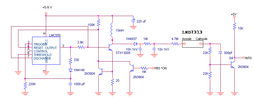
The rest of the circuit consists of an 8x2 LCD, with DB4-7 attached to PA4-7; RS and E are attached to PB0 and 1. Two pushbuttons are attached to PA1 and PA2 (pullups on). RS232 output is bit-banged and sent to PA0 at 9600 baud. PA0 is connected to RX on an FTDI USB to serial chip on a breakout board, which also powers the entire circuit. I used a 4.194304 MHz crystal, which conveniently divides
to 1 second.
Hope this is useful!
Jim
MAIN PROGRAM
// Geiger Counter
// ATtiny26 version
// Jim Remington, sjames_remington at yahoo.com
// March 2009

/* pin assignments
PA0	- 	TXD
PA1	-	Sw1
PA2	-	Sw2
PA3 -
PA4-7	LCD data
PB0-1	LCD control
PB3-	HV/LED on/off
PB4-5`	Xtal
PB6-	Count in (Int0)
PB7-	Reset
*/


#include <avr/io.h>
#include <avr/interrupt.h>
#include <avr/pgmspace.h>
#include <stdlib.h>
#include <string.h>

#define F_CPU 4194304UL
#include <util/delay.h>

#define BAUD 9600

#define ARRAY_UPPERBOUND(array)   ((sizeof(array) / sizeof(array[0])) - 1)
#define LCD_clear  	LCDSendCommand( LCD_Clear );

typedef void (*FuncPtr)(void);

void MAIN_TopMenu(void);
void Options(void);
void Start(void);
void SetPer(void);
void SetRS(void);
//void SetHV(void);
void SetCycle(void);
void DisplayClock(void);

uint8_t getkey(void);

void Delay1ms(uint8_t loops);
void Delay10ms(int loops);


	// Setup menu options
const char	SetPerStr[] 	        PROGMEM = " Period";
const char  SetCycleStr[]			PROGMEM = " Cycle";
const char	SetStartStr[]   	    PROGMEM = " Start";

const char*   SetFunctionNames[]	PROGMEM = {SetPerStr, SetCycleStr, SetStartStr};
const FuncPtr SetFunctionPtrs[]		PROGMEM = {SetPer, SetCycle, Start};

	// Messages and Settings
const char	Version[]				PROGMEM = "Cntr 1.0";
const char	Total[]					PROGMEM = " Total";
const char 	PeriodOpts[5][7]		PROGMEM = {"10 sec"," 1 min","10 min","  1 hr"," 10 hr"};
const char  CycleOpts[2][7]			PROGMEM = {"1-shot", "Repeat"};
const char	RTC_zero[]				PROGMEM = "000000";
const unsigned int	PeriodInSeconds[]			PROGMEM	= {10,60,600,3600,36000};

//globals (some others in LCD_Joystick)

static volatile uint8_t	PeriodVal=4;	//default count period = 10 seconds (2nd to last digit in RTC_buffer)
static volatile uint8_t	HV=0;			//HV on/off = auto (0) or continuously on (1)
static volatile uint8_t	RS232=1;		//RS232 on/off (1 = on, 0 = off)
static volatile uint8_t Cycle=0;		//recycle count = continuous (1) or 1-shot (0)
static volatile uint16_t event_count;	//global counter for geiger tube
static volatile char display_buf[9];

#include "lcd.c"
#include "RTC99.c"
#include "suart.c"

#define KEY_MENU  (1<<PA2)
#define KEY_ENTER (1<<PA3)


int main(void)
{

static uint8_t CurrFunc = 0, key = 0;

	PORTA |= (1<<PA2)|(1<<PA3);		//turn on pullups for switches

	DDRB |= (1<<PB3);				//enable HV output
	PORTB |= (1<<PB3);				//HV off
	Delay10ms(50);

	TX_init();				//test RS232 timing
/*
	DDRA |= (1<<PA2);	//pa2 output for synch
	PORTA &=~(1<<PA2); //zero
	_delay_us(10);
	while(1) {
	PORTA |= (1<<PA2);	//one to synch scope
	TX_putc('P');		// send a 'U' 1010101010
	PORTA &= ~(1<<PA2);  //turn off synch
	_delay_us(10);
	}
*/
	LCD_Init();
	sei();

	LCD_SendCommand(LCD_Clear);			//Show version number
	LCD_puts_f(Version);

// display default menu selection

	LCD_GotoXY(1,1);
	LCD_puts_f((char*)pgm_read_word(&SetFunctionNames[CurrFunc]));

//  setup menu

	for (;;)
	{
	key = getkey();
		if (key)
		{

		if (key == KEY_MENU)
            (CurrFunc == ARRAY_UPPERBOUND(SetFunctionPtrs))? CurrFunc = 0 : CurrFunc++;
		else if (key == KEY_ENTER)
			((FuncPtr)pgm_read_word(&SetFunctionPtrs[CurrFunc]))(); // Execute associated subroutine

// print text associated with currently selected function

		LCD_SendCommand(LCD_Clear);			//Show version number
		LCD_puts_f(Version);
		LCD_GotoXY(1,1);
		LCD_puts_f((char*)pgm_read_word(&SetFunctionNames[CurrFunc]));
       }
   }
	return 0;
}


void SetPer(void)
{
	static uint8_t CurrPer=0;
	char key;

// print text associated with currently selected period option
		LCD_SendCommand(LCD_Clear);
		LCD_puts_f(SetPerStr);
		LCD_GotoXY(1,1);
		LCD_puts_f(PeriodOpts[CurrPer]);

	for (;;)
	{
    key = getkey();
     if (key)
      {

         if (key == KEY_MENU)
           (CurrPer == ARRAY_UPPERBOUND(PeriodOpts))? CurrPer = 0 : CurrPer++;
         else if (key == KEY_ENTER)
         	{
			PeriodVal=4-CurrPer;
			return;
			} 		//time base digit in RTC_buffer

// print text associated with currently selected period option
		LCD_GotoXY(1,1);
		LCD_puts_f(PeriodOpts[CurrPer]);
       }
	}
}
/*
 NAME:      | Start
 PURPOSE:   | Measure and display counts on PORTB.6
 ARGUMENTS: | None
 RETURNS:   | None
*/
void SetCycle(void)
{
	static uint8_t CurrCycle=0,key;

// print text associated with currently selected Cycle option (default=continuous)

		LCD_SendCommand(LCD_Clear);
		LCD_puts_f(SetCycleStr);
		LCD_GotoXY(1,1);
		LCD_puts_f(CycleOpts[CurrCycle]);

	for (;;)
	{
    key = getkey();
     if (key)
      {
         if (key == KEY_MENU)
           (CurrCycle == ARRAY_UPPERBOUND(CycleOpts))? CurrCycle = 0 : CurrCycle++;
         else if (key == KEY_ENTER)
           {Cycle=CurrCycle; return;} 		//global Cycle flag,  1 = continously repeat

// print text associated with currently selected Cycle option
		LCD_GotoXY(1,1);
		LCD_puts_f(CycleOpts[CurrCycle]);
       }
	}
}

/*
** Interrupt INT0 hander
*/
ISR (INT0_vect)
{
	event_count++;
}

/*
** Start (and continue) the count
*/

void Start(void)
{
		char test,key,test2;

		if(RS232)
		{
//	write RS232 header
		TX_puts("Period= ");
		TX_puts(utoa(pgm_read_word(&PeriodInSeconds[4-PeriodVal]),(char*)&display_buf,10));
		TX_putc(0x0D);TX_putc(0x0A); //dos line terminator
		}

		PORTB &= ~(1<<PB3);					//HV on
		Delay10ms(10);						//wait for HV to rise

		MCUCR |= (1<<ISC01);				//interrupt on INT0 falling edge
		GIMSK |= (1<<INT0);					//enable INT0

		do
		{
			RTC_Init();
			event_count = 0;
			event_secs = 0;
			test=RTC_buffer[PeriodVal];
			key=0;

			while (test==RTC_buffer[PeriodVal])
				{
 					test2=RTC_buffer[5]; 	//get secconds
					LCD_SendCommand(LCD_Clear);

					display_buf[0]='>'; //Counting...
	   				utoa(event_count,(char*)&display_buf[1],10);	//convert to ascii
					LCD_puts((char*)&display_buf); 				// and display
	   				utoa(event_secs,(char*)&display_buf,10);	//seconds count to ascii
					strcat((char*)&display_buf,"s");
					LCD_GotoXY(1,1);
					LCD_puts((char*)&display_buf); 				// and display

					while (test2==RTC_buffer[5])		// hang until seconds digit changes
						{
						key=getkey();
						if (key) break;				//break on button push
						}
					test2=RTC_buffer[5];
					if (key) break;
					}
			if(key) break;

			if(RS232)
				{	//send count to serial port
				TX_puts(utoa(event_count,(char*)&display_buf,10));
				TX_putc(0x0D);	TX_putc(0x0A);  //line term
				}
// 		show total

			LCD_SendCommand(LCD_Clear);
			LCD_puts_f(Total);
			utoa(event_count,(char*)&display_buf[0],10);	//convert to ascii
			LCD_GotoXY(1,1);
			LCD_puts((char*)&display_buf); 				// and display
			Delay10ms(300);

		} while (Cycle);

//		one shot only

		if(!HV) PORTB |= (1<<PB3);		//turn HV off if "Auto"
		GIMSK &= ~(1<<INT0);			//INT0 interrupts off
		LCD_GotoXY(7,1);
		LCD_SendData('.');
		LCD_GotoXY(7,1);
		while(!getkey());							// wait for button press

		return;
}


/*
**	getkey -- returns key(s) pressed, debounced.
*/

#define BUTTONS ((1<<PA2)|(1<<PA3))

uint8_t getkey(void)
{
	char key;
	key = ~PINA & BUTTONS;			//Read Port A, nonzero if either PA2 or PA3 grounded
	if (!key) return 0;						//none pressed

	Delay10ms(2);							// debounce the press
									//reread Port A, nonzero if same key pressed
	if (!(~PINA & key)) return 0;			//none pressed

	do
	{
		while ((~PINA & key));			// wait for button to be released
		Delay10ms(1);					// debounce the release
	}
	while ((~PINA & key));				// if still not released, loop
	return key;
}

/*
 NAME:      | Delay10ms
 PURPOSE:   | Delays for specified blocks of 10 milliseconds
 ARGUMENTS: | Number of blocks of 10ms to delay
 RETURNS:   | None
*/
void Delay10ms(int loops)
{

   while (loops--)
     _delay_ms(10);
}

[/code]

SUPPORT ROUTINES
[code]/*****************************************************************************
**   Initial Author(s)...: ATMEL Norway
**   Rewritten for global BCD display buffer (RTC_buffer[])
**   the digits of which provide system-wide timers for:
**   1 second, 10 seconds, 1 minute, 10 minutes, 1 hour, 10 hours
**   Jim Remington sjames_remington at yahoo.com
**   March 2009
**   ATtiny26 version, counts to 99 hours 59 min, 59 sec
******************************************************************************/

//#include <avr/io.h>
//#include <avr/interrupt.h>
//#include <util/delay.h>

volatile char RTC_buffer[] = "000000"; 	//global BCD clock buffer
volatile unsigned int event_secs=0;

/******************************************************************************
*
*   Function name:  RTC_init
*
*   returns:        none
*
*   parameters:     none
*
*   Purpose:        Setup and start Timer/Counter 1 for one second interrupt @ 4.096 MHz.
*
*******************************************************************************/

void RTC_Init(void)
{

    cli();					// disable global interrupts
    TCNT1 = 0;              // clear TCNT1
    TCCR1A = 0;			// select precaler:4.1943 MHz / 16384 = 256 Hz
 	TCCR1B = 0x0F;
	TIFR   = (1<<TOV1);		// Clear Timer1 OVF interrupt flag
    TIMSK = (1<<TOIE1);	// enable Timer1 overflow interrupt

	strcpy_P((char*)&RTC_buffer[0],RTC_zero);	//initialize clock to zeros

    sei();					// enable global interrupt
}

/*****************************************************************************
*
*   Function name : ShowClock
*
*****************************************************************************/
/*
void ShowClock(void)
{

	LCD_SendCommand(LCD_Clear);
	LCD_puts((char*)&RTC_buffer[0]);
}
*/

/*
** handle Timer 1 overflow interrupt (1 per second)
*/

ISR (TIMER1_OVF1_vect)
{
	uint8_t i;
	char t[6];

	for (i=0;i<6;i++) t[i]=RTC_buffer[i];	//make a copy, so digits don't change more than once on rollover

    t[5]++;		// increment second
	event_secs++;

    if (t[5] > '9')
	{
		t[5]='0';	// increment ten seconds
		t[4]++;
	 	if ( t[4] > '5')
		{
			t[4]='0';
			t[3]++;			// increment minutes
    		if (t[3] > '9')
    		{
				t[3]='0';
				t[2]++;		// increment ten minutes

		 		if (t[2] > '5')
				{
					t[2]='0';
					t[1]++;			// increment hours
 	     			if (t[1] > '9')
					{
						t[1]='0';
						t[0]++;		// increment ten hours
						if (t[0] > '9') t[0]='0';
    				}
				}
			}
		}
	}
	for (i=0;i<6;i++) RTC_buffer[i]=t[i];  //copy updated time
}

// suart.c
// TX = PORTA.0
// 8N1
#define BAUD 9600
#define US_BIT 1000000UL/BAUD
// microseconds per bit


void TX_init(void)
{
   DDRA |= 1;               //PORTA.0 = output
   PORTA |=1;            //TX idle
}

void TX_putc(unsigned char c)
{
   char i,t;
   t=c;                  //copy character to send
   cli();                  //disable interrupts

   PORTA &= ~1;            //start bit
   _delay_us(US_BIT);        //0.41667ms for 2400 baud

    for (i=0; i<8; i++)
   {

   if ( t & 0x01 ) PORTA |= 1;   // If the LSB of char=1, set logic 1 on TX_PIN
   else PORTA &=~1;         // Otherwise: send 0

   _delay_us(US_BIT);

   t >>= 1;               // shift TX buffer right
   }

   PORTA |=1;               //send stop bit
   _delay_us(US_BIT);
   sei();                     //enable int
}

void TX_puts(char *data )
{
  while(*data != 0) TX_putc( *data++ );
}

// lcd.c
/*
** LCD Routines with bargraph display, heavily modified from Pascal Stang's avrlib
** Original LCD routines heavily modified from examples posted on Pololu user forum
** sjames_remington /at/ yahoo.com
** ATtiny26 4 MHz version March 2009
** PORTA 4,5,6,7 = DB 4-7
** PORTB 0,1 = E, RS.   R/W is grounded
*/

//#define F_CPU 4000000UL

#define RS   PB1
#define E   PB0

#include <avr/io.h>
#include <util/delay.h>
#include <avr/pgmspace.h>

//char TextBuffer[10];         //global text buffer

/*

 The required delays included here are generously in accord with the LCD data sheet, and should be
 independent of the clock speed as long as F_CPU is set correctly (>= 1 MHz)

 Jim Remington, sjames_remington at yahoo dot com

*/

//Function prototypes

void LCD_Init(void);
void LCD_SendData(char);
void LCD_SendCommand(char command);
void LCD_puts(char *string);
void LCD_puts_f(const char *string);
void LCD_GotoXY(unsigned char x,unsigned char y);

// useful defines (LCD commands)

#define LCD_Clear 0x01
#define LCD_Line1 0x80
#define LCD_Line2 0xC0

/*
Send lower 4 bits of data byte to display
*/
void   LCD_SendNibble(char data )
{
   PORTA &= ~(0xF0);         //clear LCD bus bits 0-4
   PORTA |= ((data & 0x0F)<<4);   //or in data
   _delay_us(5);
   PORTB |= (1<<E);      //E = 1
   _delay_us(5);         //required minimum 1 us delay
   PORTB &= ~(1<<E);      //E = 0
   _delay_ms(0.5);         // someone suggested 4.1 ms here, this worked.
}

/*
Send a character to the LCD display
*/

void   LCD_SendData(char data )

{
   PORTB |= (1<<RS);      //RS = 1;
   LCD_SendNibble( data >> 4 );
   LCD_SendNibble( data );
   _delay_us(100);         //38 us typically needed to complete this action
}

/*
Send a command to display. Required delay time depends on the command and the
LCD controller clock frequency -- here assumed to be the minimum 190 kHz
*/
void   LCD_SendCommand(char command )

{
   PORTB &= ~(1<<RS);      // RS = 0
   LCD_SendNibble(command >> 4 );
   LCD_SendNibble(command);
   _delay_ms(2);         //maximum required is 2.1 ms for "clear display"
}

// print a string constant

void   LCD_puts(char *str )
{
    while (*str != 0) LCD_SendData( *str++ );
}

void LCD_puts_f(const char *FlashData)
{
// Print data from program memory

   strcpy_P((char*)&TextBuffer[0], FlashData);
   LCD_puts(TextBuffer);
}
// set print position to (x,y) where y=line number (0 or 1), x = character position 0, 1, etc.

void LCD_GotoXY(unsigned char x, unsigned char y)
{
   volatile unsigned char ddram_addr;
   ddram_addr=0x80;         //initialize data ram address to 0 (default)
   if (y) ddram_addr=0xC0;     // else start print at line 2, DDRAM address 0x40
   LCD_SendCommand(ddram_addr+ (x&0x7F) );
}
/*
Initialize the LCD Display, timing requirements taken from datasheet
Set PORTA 4-7 to DB 4-7
Set PORTB 0,1 to E, RS

Sends required start-up sequence to set 4 bit interface, 2 lines, 5x8 characters and clear display
*/

void   LCD_Init( void )
{
   DDRA |= 0xF0;               //data bus bits = PB4-7 output
   DDRB |= (1<<RS)|(1<<E);         //RS, E output
   PORTB &= ~( (1<<RS)|(1<<E) );   // E=0,RS=0
   _delay_ms(10);         //required startup sequence from power-on (see datasheet)
   _delay_ms(10);         // 2x10 because max delay is 16 ms at 16 MHz
   LCD_SendNibble(0x03);   //set interface=8 bits
   _delay_ms(10);         //wait at least 5 ms
   LCD_SendNibble(0x03);   //set interface=8 bits
   _delay_ms(1);         //wait at least 100 us
   LCD_SendNibble(0x03);   //set interface=8 bits
   _delay_ms(1);         //wait at least 100 us
   LCD_SendNibble(0x02);   //set interface=4 bits
   _delay_ms(1);         //delays after this are built into SendCommand
   LCD_SendCommand(0x28);   //set interface=4 bits, 2 lines, 5x8 characters
   LCD_SendCommand(0x08);   //display off, cursor off, blink off
   LCD_SendCommand(0x01);   //clear display
   LCD_SendCommand(0x06);   //entry mode set, cursor shifts right after character rcvd.
   LCD_SendCommand(0x0D);   //0b01DCB  D=1:Display on, C=1:cursor on, B=1:Blink on
// the above commands move cursor due to autoinc. So clear display again:
//   LCD_SendCommand( LCD_Clear );
}