Turning pins on and off (ALL ISSUES SOLVED!)

I read the post with a similar subject but it left out so much or I was too confused so I couldn’t see how to accomplish turning a pin on or off. I too am trying to use a transistor (tied to a relay) to control a higher voltage. I have tried setting the pin as both an input (using a positive link value) and an output (using a neg link value), as well as setting the link value to 0. I have tried every possible combination of setDigitalOutput() and setDigitalInput() with all 3 link values and all I can get is the pin starting and remaining high (and thus the relay trips). (Note: I want to eventually control a solenoid but am testing with an LED.)

What is the magic combination for doing this?

Thanks,

Burke

I wanted to add that I have tried this on pins P1_4, P1_5 and P1_6 without success and that the program I have loaded is based on the io_repeater example program.

Also, I have successfully used the program to turn pins P0_4 and P0_5 on or off on another Wixel by using hand operated switches attached to P0_2 and P0_3 on the Wixel being discussed in this post.

Hello, Burke.

It is hard for me to understand what you are trying to do. Could you tell me what forum post you are referring to? Could you also tell me how many Wixels you have and what settings you chose for each of them? Lastly, could you tell me what you expect to happen and what is actually happening? Without these details, it would be difficult to help you.

I am not sure what kind of modifications you have made to the I/O Repeater source, but it seems like your link values have not been set correctly. If you set a positive link value for a pin, the pin will become an output (0 V if not connected). Conversely, if you set a negative link value for a pin, then the pin becomes an input. Every pin configured as an input has an internal 20 kΩ pull-up resistor except P1_0 and P1_1, which float when they are inputs. This means that if you leave the input pin disconnected, it will be pulled high (3.3 V) by default. Instead of modifying the I/O Repeater app, could you download the code from here and see if it works for you? Documentation regarding the I/O Repeater app can be found here.

-Taylor

Taylor,

Thanks for your reply.

The app you sent me works as the doc says.

The other post I refered to is:

"Turning LEDS (and pins) On and Off "
by Louie » Thu May 05, 2011 11:08 am

What I have done is set up 2 wixels, say wixel 1 and 2. Both are loaded with a program very similar to io_repeater. The program has only been altered to allow me to use two switches attached to wixel 1 to turn on a couple of lights on wixel 2. That part works fine now.

But now what I want to do is have a solenoid turn one of the switches on wixel 1 off given a certain set of conditions (the conditions are not implemented yet and are not important to the current problem). Thus I am NOT trying to control the solenoid on a remote wixel but rather have conditions that are detected on wixel 1 trigger a solenoid attached to wixel 1. So this action can be tested using only one wixel. For now I have replaced the solenoid by an LED and am attempting to write code that will turn the LED on or off using only wixel 1. I am trying to use P1_6 to turn the LED on/off and have so far failed.

I am testing by trying to turn the LED on for 2 seconds then turn it off and repeat that about 5 times.

To do this I am using repeated calls to the function
releaseSolenoid(2000);

#define SIGNAL_RELEASE_SOLENOID_INDEX 12

void releaseSolenoid(int nDelay)
{
	// extend (energize) solenoid to push switch to OFF position (turn ON LED in test config)
        setDigitalOutput(pins[SIGNAL_RELEASE_SOLENOID_INDEX], HIGH);
//	setDigitalInput(pins[SIGNAL_RELEASE_SOLENOID_INDEX], FALSE); // not sure which call to use here
	// give some time for switch to move
	delayMs(nDelay);
	 // release solenoid (turn OFF LED in test config)
	 setDigitalOutput(pins[SIGNAL_RELEASE_SOLENOID_INDEX], LOW);
//	setDigitalInput(pins[SIGNAL_RELEASE_SOLENOID_INDEX], TRUE); // not sure which call to use here
}

NOTE: FALSE and TRUE are defined elsewhere in code.

links are set as follows:

/** Parameters ****************************************************************/
int32 CODE param_P0_0_link = 0;
int32 CODE param_P0_1_link = 0;
int32 CODE param_P0_2_link = -2; // to turn light 1 on using wixel 1
int32 CODE param_P0_3_link = -1; // to turn light 2 on using wixel 1
int32 CODE param_P0_4_link = 2; // light 1 on wixel 2 attached to this pin
int32 CODE param_P0_5_link = 1; // light 2 on wixel 2 attached to this pin
int32 CODE param_P1_0_link = 0;
int32 CODE param_P1_1_link = 0;
int32 CODE param_P1_2_link = 0; 
int32 CODE param_P1_3_link = 0; 
int32 CODE param_P1_4_link = 0; 
int32 CODE param_P1_5_link = 0; 
int32 CODE param_P1_6_link = -3; // test LED (Wixel's 3.3V signal causes transistor to switch
						//	which activates 6A relay that controls 12V to LED)
                                                // NOT SURE HOW OR IF THIS LINK SHOULD BE SET

int32 CODE param_P1_7_link = 0;
int32 CODE param_P2_1_link = 0; // red LED

I hope this makes it a little clearer what I am doing.

Taylor,

I was able to get this to work. I had to set the P1_6 link to 0 and used the code as is shown above except I added a delay after each call to releaseSolenoid(2000). I guess the LED was being turned back on so quickly by the next call to releaseSolenoid(2000) that the LED didn’t even have time to flicker - now it stays off for 2 seconds or so like it should.

Sorry for the false alarm but perhaps someone else will be able to gain something by all the thrashing around I did.

I am glad you solved your problem; thanks for letting me know what was wrong!

-Taylor

I thought I had solved the problem I was having… but NO!!!

I was running the program on the Wixel and suddenly the Wixel died - the green light went out. I tried letting it sit for awhile but it was gone.

I substituted another Wixel and loaded the program and now it does not work. I have no idea why it worked before but does not work now - the fact that the Wixel failed makes me think there may have been some kind of damage to it that allowed my program to work.

Anyway, I am back to square 1 again. Now the voltage on P1_6 always seems to read 0.0V - so I tried using P1_7. P1_7 reads 3.3V when not hooked to anything but when I hook it to the 2N3904 transistor (used as a switch to energize the coil on a relay), the voltage drops to something like 0.7V - this is not enough to cause the transistor to switch right away but after 20 or 30 seconds the voltage slowly drops to around 0.68V and it switches. If I hook the transistor to the 3V3 pin it works fine (it switches right away) - so the transistor switching part of the circuit is OK. My calls to releaseSolenoid(), that caused it to switch on and off before, now have no effect on the pin’s voltage.

How do I get P1_7 (or any other pin) to have a solid, usable and controllable 3.3V on it?

HELP!

I’m sorry you’re still having trouble. You might want to try forcing the Wixel into bootloader mode to see if you can get it to respond again. Directions for resetting the Wixel can be found here. I am also unsure of what code you are using at this point, so could you repost your entire program using code brackets ?

You might want to try using pins 1_0 and 1_1 to drive your transistor, since they provide more current than the other I/O pins. However, I suspect that your circuit is trying to draw more current than the Wixel I/O pins can provide. Could you post a schematic and photos of your entire setup clearly showing all the connections?

-Taylor

I was able to get the failed Wixel in bootloader mode (the yellow and green LEDs were both on) when I plug in the Wixel the green light now comes on but the Wixel does not show up on the Wixel config utility and refresh does not make it show up.

Using a new Wixel for testing. I am using the following code for this test. As it is now, I am using P0_0 to control the transistor. It appears that it may be resetting the Wixel because after I load the code the wixel disappears from the config util for a half minute or so then reappears - but it may just be a delay due to config util itself.

This code does NOT flash the LED at 2 sec. intervals as expected. LED comes ON when code starts running on Wixel and never goes OFF. The voltage when the LED is ON is 3.0V at P0_0 - so that is good.


/** io_repeater app (altered for my use):

wireless capabilities not used for this test - only used a single wixel.

*/

/** Dependencies **************************************************************/
#include <cc2511_map.h>
#include <board.h>
#include <usb.h>
#include <usb_com.h>
#include <random.h>
#include <time.h>
#include <gpio.h>
#include <radio_queue.h>

#define MAX_TX_INTERVAL 10 // maximum time between transmissions (ms)

#define PIN_COUNT 15
static uint8 CODE pins[PIN_COUNT] = {0, 1, 2, 3, 4, 5, 10, 11, 12, 13, 14, 15, 16, 17, 21};

// macros to determine whether a pin is an input or output based on its link param
#define IS_INPUT(pin)  (pinLink(pin) < 0)
#define IS_OUTPUT(pin) (pinLink(pin) > 0)

// list and count of input pins
static uint8 XDATA inPins[PIN_COUNT];
static uint8 inPinCount = 0;

// list and count of output pins
static uint8 XDATA outPins[PIN_COUNT];
static uint8 outPinCount = 0;

// only tx if we have at least one input; only rx if we have at least one output
static BIT txEnabled = 0;
static BIT rxEnabled = 0;

// In each byte of a buffer:
// bit 7 = pin value
// bits 6:0 = pin link
#define PIN_LINK_OFFSET 0
#define PIN_LINK_MASK 0x7F
#define PIN_VAL_OFFSET 7

/** Parameters ****************************************************************/
int32 CODE param_P0_0_link = 0;
int32 CODE param_P0_1_link = 0;
int32 CODE param_P0_2_link = 0;
int32 CODE param_P0_3_link = 0;
int32 CODE param_P0_4_link = 0;
int32 CODE param_P0_5_link = 0;
int32 CODE param_P1_0_link = 0;
int32 CODE param_P1_1_link = 0;
int32 CODE param_P1_2_link = 0;
int32 CODE param_P1_3_link = 0;
int32 CODE param_P1_4_link = 0;
int32 CODE param_P1_5_link = 0;
int32 CODE param_P1_6_link = 0; // solenoid (LED in test) (Wixel's 3.3V signal causes transistor to switch
						//		which activates 6A relay that controls 12V to LED)
int32 CODE param_P1_7_link = 0;
int32 CODE param_P2_1_link = 0; // red LED

#define TRUE 1
#define FALSE 0

#define SIGNAL_RELEASE_SOLENOID_INDEX 0

void releaseSolenoid(int nDelay);
void initSignalVars();

/** Functions *****************************************************************/
void updateLeds()
{
    usbShowStatusWithGreenLed();

    LED_YELLOW(vinPowerPresent());
}

int8 pinLink(uint8 pin)
{
    switch(pin)
    {
    case 0:  return param_P0_0_link;
    case 1:  return param_P0_1_link;
    case 2:  return param_P0_2_link;
    case 3:  return param_P0_3_link;
    case 4:  return param_P0_4_link;
    case 5:  return param_P0_5_link;
    case 10: return param_P1_0_link;
    case 11: return param_P1_1_link;
    case 12: return param_P1_2_link;
    case 13: return param_P1_3_link;
    case 14: return param_P1_4_link;
    case 15: return param_P1_5_link;
    case 16: return param_P1_6_link;
    case 17: return param_P1_7_link;
    case 21: return param_P2_1_link;
    }
    return 0;
}

void configurePins(void)
{
    uint8 pin, tmp;

    // Set all pulled pins to high
    // TODO: make this user-configurable
    setPort0PullType(HIGH);
    setPort1PullType(HIGH);
    // Port 2 is pulled low and should remain pulled low; pulling it high would cause problems.

    for(pin = 0; pin < PIN_COUNT; pin++)
    {
        tmp = pins[pin];

        if (IS_OUTPUT(tmp))
        {
            // This pin is configured as an output, so add it to the list of output pins.
            // The default state of the output pins, as documented in the user's guide, is LOW.
            setDigitalOutput(tmp, LOW);
            outPins[outPinCount++] = tmp;
            rxEnabled = 1;
        }
        else if (IS_INPUT(tmp))
        {
            // This pin is configured as an input, so add it to the list of input pins.
            // The pin is already an input because all pins are inputs by default.
            inPins[inPinCount++] = tmp;
            txEnabled = 1;
        }
    }
}

// read the states of input pins on this Wixel into a buffer
void readPins(uint8 XDATA * buf)
{
    uint8 pin;

    for (pin = 0; pin < inPinCount; pin++)
    {
        // put pin link in lower 7 bits, read pin state and put in highest bit
        buf[pin] = (-pinLink(inPins[pin]) << PIN_LINK_OFFSET) | (isPinHigh(inPins[pin]) << PIN_VAL_OFFSET);
    }
}

// set the states of output pins on this Wixel based on values from a buffer
void setPins(uint8 XDATA * buf, uint8 byteCount)
{
    uint8 byte, pin;

    // loop over all bytes in packet
    for (byte = 0; byte < byteCount; byte++)
    {
        for (pin = 0; pin < outPinCount; pin++)
        {
            // check if this output pin's link matches the link in this packet
            if ((uint8)pinLink(outPins[pin]) == ((buf[byte] >> PIN_LINK_OFFSET) & PIN_LINK_MASK))
            {
                // if so, set the pin state based on the val bit
                setDigitalOutput(outPins[pin], (buf[byte] >> PIN_VAL_OFFSET) & 1);
            }
        }
    }
}

void main(void)
{
    // pointers to link packets
    uint8 XDATA * txBuf;
    uint8 XDATA * rxBuf;

    uint8 lastTx = 0;

    systemInit();
    usbInit();

    radioQueueInit();

    configurePins();
	releaseSolenoid(2000);
	delayMs(2000);
	releaseSolenoid(2000);
	delayMs(2000);
	releaseSolenoid(2000);
	delayMs(2000);
 	releaseSolenoid(2000);
	delayMs(2000);

	initSignalVars();

    while(1)
    {
        updateLeds();
        boardService();
        usbComService();

        // receive pin states from another Wixel and set our output pins
        if (rxEnabled && (rxBuf = radioQueueRxCurrentPacket()))
        {
            setPins(rxBuf + 1, *rxBuf);
            radioQueueRxDoneWithPacket();
        }

        // read our input pins and transmit pin states to other Wixel(s) every MAX_TX_INTERVAL milliseconds
        if (txEnabled && (uint8)(getMs() - lastTx) > MAX_TX_INTERVAL && (txBuf = radioQueueTxCurrentPacket()))
        {
            readPins(txBuf + 1);
            *txBuf = inPinCount; // set packet length byte
            radioQueueTxSendPacket();

            lastTx = getMs();
        }
    }
}

void releaseSolenoid(int nDelay)
{
	// retract solenoid to allow signal lever to return to neutral position
	setDigitalOutput(pins[SIGNAL_RELEASE_SOLENOID_INDEX], HIGH);
//	setDigitalInput(pins[SIGNAL_RELEASE_SOLENOID_INDEX], PULLED);
	// give some time for lever to move
	delayMs(nDelay);
	// release solenoid
	setDigitalOutput(pins[SIGNAL_RELEASE_SOLENOID_INDEX], LOW);
//	setDigitalInput(pins[SIGNAL_RELEASE_SOLENOID_INDEX], HIGH_IMPEDANCE);
}

void initSignalVars()
{
	setDigitalOutput(pins[SIGNAL_RELEASE_SOLENOID_INDEX], LOW);
}

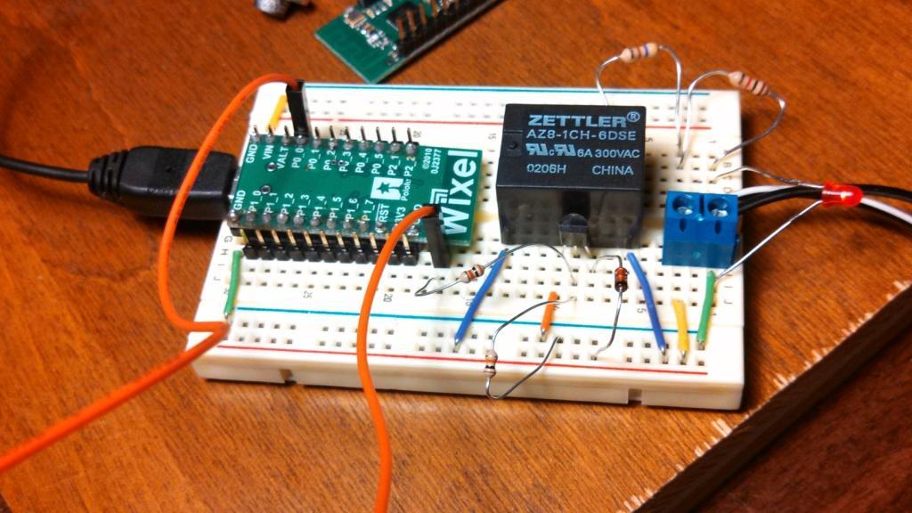
Picture of hardware setup is attached.


schematic attached as pdf

Wixel_test.pdf (11.8 KB)

The reason that the Wixels cannot be recognized by the configuration utility for about half a minute is that you are not calling usbService for the first 16 seconds as your app runs. That method needs to be called frequently to have a functioning USB connection.

From what you said in the last post, it sounds like the voltage on P0_0 is going high when the Wixel starts and staying high. However, the code you wrote is supposed to drive P0_0 high (3.3 V) for 2 seconds, then drive it low (0.0) for 2 seconds, and repeat four times. It looks like your code should work, however it might be easier to use a simpler program. Could you load this code and test your circuit again using P0_0?

(This is a modified version of our example_blink_led app. It should toggle P0_0 every 2 seconds.)


#include <wixel.h>
#include <usb.h>
#include <usb_com.h>
#include <stdio.h>

int32 CODE param_blink_period_ms = 4000;

uint32 lastToggle = 0;

void updateLeds()
{
    usbShowStatusWithGreenLed();

    LED_YELLOW(0);

    if (getMs() - lastToggle >= param_blink_period_ms/2)
    { 
        LED_RED(!LED_RED_STATE);
        setDigitalOutput(0, LED_RED_STATE);
        lastToggle = getMs();
    }
}

void main()
{
    systemInit();
    usbInit();

    while(1)
    {
        boardService();
        updateLeds();
        usbComService();
    }
}

-Taylor

Thank you very much for the suggestion - it gave me the idea I needed to solve the problem.

I used your code and it worked as far as blinking the LED. I then changed my old code to get it to blink the LED just once. It seems that you must regularly run the code in the while (1) loop in main() to make the blinking work. So I used code similar to the blinker code you provided to keep track of the length of the delay time - instead of using a delayMs() call which stops the while (1) loop.

My code for the function that turns on the LED (previously called releaseSolenoid()) is as follows:

// this is called from within the while(1) loop in main()
void switchLed(int nDelayMs)
{
	if (bTurnOnLed) // this var is set by the calling code
	{
		setDigitalOutput(SIGNAL_RELEASE_SOLENOID_INDEX, HIGH);
		bTurnOnLed = FALSE;  // so it won't try to turn on LED next time through
                // note when LED was turned on to get proper delay time
		uLedOnTime = getMs();
                // we have turned LED on and now set up to turn it off
		bTurningLedOff = TRUE;
	}
	// Turn off LED after specified delay
	else if (bTurningLedOff && (getMs() - uLedOnTime >= nDelayMs))
	{
		// turn off LED
		setDigitalOutput(SIGNAL_RELEASE_SOLENOID_INDEX, LOW);
		bTurningLedOff = FALSE;
	}
}

Now I need to read the voltage on PO_1 to know when to turn on the LED. I am using a hall effect sensor to detect when a magnet passes by. When the magnet passes the hall effect sensor it switches the external voltage applied to P0_1 from 3.3V to 0.0V. I want to use adcRead(1) to read the voltage on P0_1 in order to detect the magnet moving by the hall effect sensor. I added a call to adcRead(1) to my version of io_repeater. I tried including wixel.h and/or adc.h and compiling. I get the following error on linking:

?ASlink-Warning-Undefined Global ‘_adcRead’ referenced by module ‘io_repeater’

I assume I need to link the adc library but I don’t know how to do it. I can’t find where link libraries are specified. I am using eclipse helios and GCC, etc.

Thanks again.

Since you are trying to use functions in the Wixel’s adc library, you are going to want to add the GNU Make variable in your options.mk file called APP_LIBS and add the file name adc.lib. Linking libraries to your Wixel app is described under the “Creating Your Own App” section in the Wixel’s SDK Documentation.

If this advice does not work you, could you tell me how you are compiling your app and the absolute path of your source code? Could you also tell me what files are included in the directory that contains your source code? Did you follow the instructions in the Wixel’s User’s Guide for building with Eclipse?

-Taylor

Thanks that worked! It linked with the call to adcRead().

However, I had decided to try using isPinHigh() instead of using adcRead() to read the voltage and it worked - but it is good to know how to add a link library to a project.

Now I have ANOTHER question: How do I detect when a switch is closed and grounds a pin? The pin has a neg link ID and transmits its state (it goes high) to another Wixel (as expected).

As noted above, my voltmeter indicates that the pin does go high when the pin is grounded and is 0V when not grounded. But despite the apparent voltage change, isPinHigh() returns true whether the pin is grounded or not. Do I need to use a different function or method to detect this?

It is odd that you said that isPinHigh works but that “isPinHigh returns true” whether the switch is grounded or not. How is it working if the function is not changing state? Could you tell me how your switch is wired when it is attached to ground? Could you also tell me how your switch is wired when it is not attached to ground? Also could you tell me exactly which pin you are measuring and what your voltage meter terminals are attached to when you are measuring that voltage? Could you also tell me the exact voltage measured when the pin is in a “High” state?

It is also confusing to me that since isPinHigh returns true all the time, that you are measuring 0 V. 0 V corresponds to the pin being in a low state. How did you determine that isPinHigh returns true? Since it sounds like that you have changed your setup since the last post, could you send me a schematic and photos of your new setup? Could you also post the full program that you have modified as well?

Lastly, you should not need a different function to detect the state of a switch. isPinHigh should work fine for detecting whether the switch is off or on.

-Taylor

Taylor,

As I was preparing the schematic and my code to post I found a bug in my code - I was using the wrong pin number in one case and the correct one in another. That is why isPinHigh() worked in detecting the input to P0_1 from the hall effect sensor but appeared not to work for the switches attached to P1_2 and P1_3. I think I finally have all the pieces I need to finish my project.

Thank you very much for your patience and help.

Burke