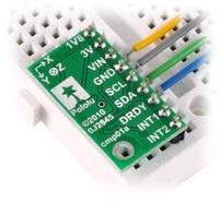
LSM303DLH Magnetometer Problem

Just received the LSM303DLH breakout board today. Hooked it up to my dsPIC and I’m not able to read anything from the magnetometer. It’s not clear if the configuration commands are being read at all. When querying the data registers it returns 0xFF for each. I’m powering the board at 3.3V. Set to normal operation at 75Hz output. I’m attempting to read the registers at 50Hz. The DRDY pin is at 1.8V, so it seems like something may be happening. I’ve scoped the I2C lines and the address and register bytes look clean, the pins then stay high. Code is below for reference…

Also, I’m able to communicate with the accelerometer just fine. The accelerometer output is a bit odd in that the results are shifted 4 bits from what I expect. At ±8g resolution the 1g values are about 4096 instead of 256… Has anyone else seen this? It’s not indicated in the datasheet, but is easy enough to deal with.

Best,
Geoff

Configuration:

#define MAGREAD	0x3D
#define MAGWRITE	0x3C

//////////////////////////////////////
// Configure LSM303DLH Magnetometer //
//////////////////////////////////////
void ConfigureMag(void) {

StartI2C();
IdleI2C();
MasterWriteI2C(MAGWRITE);
IdleI2C();
MasterWriteI2C(0x00); // Set pointer to configuration register
IdleI2C();
MasterWriteI2C(0b00011000); // Set to 75 Hz data ouput rate and normal configuration
IdleI2C();
StopI2C();
IdleI2C();

StartI2C();
IdleI2C();
MasterWriteI2C(MAGWRITE);
IdleI2C();
MasterWriteI2C(0x01); // Set pointer to configuration B register
IdleI2C();
MasterWriteI2C(0b10000000); // Set minimum gain (+- 4.0 Gauss range)
IdleI2C();
StopI2C();
IdleI2C();

StartI2C();
IdleI2C();
MasterWriteI2C(MAGWRITE);
IdleI2C();
MasterWriteI2C(0x02); // Mode register
IdleI2C();
MasterWriteI2C(0b00000000); // Continuous conversion mode
IdleI2C();
StopI2C();
IdleI2C();
}

Read (called at 50Hz):

/////////////////////////////////
// Read LSM303DLH magnetometer //
/////////////////////////////////
void ReadMag(StateVector *svptr) {

static unsigned char xH;
static unsigned char xL;
static unsigned char yH;
static unsigned char yL;
static unsigned char zH;	
static unsigned char zL;

StartI2C();
IdleI2C();
MasterWriteI2C(MAGWRITE); // Write address
IdleI2C();
MasterWriteI2C(0x03); // First data register
IdleI2C();
RestartI2C();
IdleI2C();
MasterWriteI2C(MAGREAD); // Read address
IdleI2C();
xH = MasterReadI2C(); // x-axis high byte
AckI2C();
IdleI2C();
xL = MasterReadI2C(); // x-axis low byte
AckI2C();
IdleI2C();
yH = MasterReadI2C(); // y-axis high byte
AckI2C();
IdleI2C();
yL = MasterReadI2C(); // y-axis low byte
AckI2C();
IdleI2C();
zH = MasterReadI2C(); // z-axis high byte
AckI2C();
IdleI2C();
zL = MasterReadI2C(); // z-axis low byte
NotAckI2C();
IdleI2C();
StopI2C();
IdleI2C();       

svptr->magX = xL|(xH << 8); 	// x-axis value
svptr->magY = yL|(yH << 8);		// y-axis value
svptr->magZ = zL|(zH << 8);		// z-axis value

Hello, Geoff.

The accelerometer readings are a 12-bit reading “left-justified” in a 16 bit space, so you have to right shift it by 4. It isn’t explicitly said in the datasheet, but you can infer it from a couple of inconsistancies in the datasheet and experimentation.

When the magnetometer reading overflows/underflows it returns -4096 on a channel, can you try increasing the sensor input field range?

- Ryan

Hi Ryan,

Thanks for confirming the behavior of the accelerometer, it’s easy enough to shift 4 bits to the right.

The magnetometer reading doesn’t appear to be overflowing, all the data bytes are just 0xFF (int value of -1). I configured it to the maximum range (± 8.1 gauss) and tried some different data rates as well with no effect. Also tried it with positive and negative biases and in single conversion mode. Still no luck…

Some more info: I’m running I2C at 400 kHz. I’m also able to communicate just fine with a bunch of other sensors on the bus (ADXL345, ITG3200, BMP085) including the LSM303 accelerometer.

Any other thoughts?

Geoff

Can you try doing I2C communication speed at 100kHz and using the default update rate (15 Hz)? Also, can you try reading magnetometer configuration bytes to see if they match what you wrote?

- Ryan

Tried 100kHz and 15 Hz, neither helped. Also tried reading the config registers, I’m getting 156 from the first register (0x00) and 0’s from the other two (0x01 and 0x02). Better than 0xFF from everything I guess… Although, I seem to be getting 156 for the first read command every time, regardless of which register it is (i.e. switching the read order, or if I read the status register).

Is there something funky about the I2C protocol for the magnetometer vs. the accelerometer? I’ve had issues in the past with the HMC5843, but they usually aren’t this weird.

Geoff

Well that is weird, can you try setting the registers one at a time and reading them immediately after you set them? Can you post a complete, minimal program that exhibits the problem you are seeing?

- Ryan

We changed our setup and have the magnetometer working now.

The best I can conclude is that the I2C timing requirements for the magnetometer aren’t as robust as for the accelerometer.

Before we had connected the LSM303DLH breakout board to a 3.3V I2C bus on an existing board, which was then level shifted to 5V to talk with the dsPIC on that board. Since the breakout board I2C lines were already being level shifted from 1.8V to 3.3V, maybe there was some signal degradation going through two level shifts? The accelerometer on the LSM303 had no problem, but the magnetometer didn’t respond properly to commands as detailed before.

Our PIC was in turn connected to Gumstix Overo (running at 1.8V) through a UART port. To cut out the middle man we connected the LSM303DLH breakout board to the I2C lines on the gumstix. Since this was also operating at 1.8V we had to solder to points on the breakout board before the SCL and SDA lines were level shifted. The breakout board was still powered at 3.3V in keeping with the 2.6 to 5.5V spec.

After figuring out how to use I2C in Linux on the Overo everything is working great!

Best,
Geoff

I’m glad you got it working and thanks for telling us what was wrong. By the way, you can connect the LSM303DLH carrier directly to a 5V I2C bus.

- Ryan

I know. Those pins weren’t broken out on our board, but the 3.3V side of the level shifter was.

What is the real problem about LSM303DLH with Magnetometer, because my accelerometer gives me readings, (programming in CCS) but only in the magnetometer gives me the three axes, the value of 65535. What is the problem with the electronics? missing some connection? some pull-ups? :cry:

This is my code

i2c_start();
i2c_write(MAG_ADDRESS_WR); //0x3C
i2c_write(MR_REG_M); //0x02
i2c_write(0x00); // (0x00);
i2c_stop();

while (TRUE)
{
i2c_start();
i2c_write(MAG_ADDRESS_WR); //0x3C
i2c_write(OUT_X_H_M); //0x03
i2c_start();
i2c_write(MAG_ADDRESS_RD); //0x3D
mxh = i2c_read();
mxl = i2c_read();
myh = i2c_read();
myl = i2c_read();
mzh = i2c_read();
mzl = i2c_read();
i2c_stop();

Mx=(mxh256)+mxl;
My=(myh
256)+myl;
Mz=(mzh*256)+mzl;

}

Is there something wrong with my code?


Re: LSM303DLH Magnetometer Problem
by gcbower on Sun May 22, 2011 2:14 am

I know. Those pins weren’t broken out on our board, but the 3.3V side of the level shifter was.

Hello.

I have been talking to mariachi1980 over email because he also emailed me his question. Here is my current understanding:

  1. He is using software I2C at 100kbps
  2. His PIC is running at 5V
  3. His problem sounds exactly like gcbower’s, so I suspect there is some problem with his I2C signals

mariachi1980 said he would investigate with an oscilloscope and try a slower clock speed.

- Ryan

Hello guys,

I’ve stuck with this same magnetometer issue. I’m trying to connect LSM303DLH to I2C bus of OMAP3530 (BeagleBoard). I have no probems reading/writing Accelerometer registers, but the Magnetometer part of this chip is not responding to I2C commands. When I scope it, I admit that once the {1Eh address + W} is sent, there is no ACK coming from magnetometer. I believe the magnetometer part of the chip is definitely not compliant with I2C standard in terms of timing, I tried it on 100, 50 and 10 kHz speed. I’m using Linux driver which in turn uses OMAP’s built-in I2C controller, i.e. all I/O is done in hardware according to I2C standard, hence timing cannot be easily altered. Can please some help me ? Thanks.

I’ve read on this same thread that gcbower was able to successfully resolve this issue with Gumstix board which is a clone of BeagleBoard based on same OMAP3530 MPU. I wonder how he did this ? Is there any kernel hack to “fix” timing ?

My setup: VDD = 3.3V, IOVCC = 1.8V, SDA and SCL of each device are combined and 5kOhm pull-up resiters added to SDA and SCL signals accordingly. No level converters added/needed.

Regards,
Ruslan.

Hi Ruslan,

We have it running at 400 kHz on our gumstix running Ubuntu 9.04. These are the steps we needed to take to get it to work:

  1. Installed i2ctools for linux from lm-sensors.org/wiki/I2CTools.
  2. Used some prebuilt modules for the gumstix following instructions here docwiki.gumstix.org/index.php/I2C_on_the_Gumstix
  3. Once these are installed we had to type “modprobe i2c-dev”
  4. This should cause the i2c buses to show up in the /dev directory. We were able to communicate with the magnetometer initially using some of the i2ctools packages just to confirm things were working.
  5. In our C code we used the standard open/read/write commands.

E.g. our initialization routine:

	int fh = open("/dev/i2c-3",O_RDWR);

	// Write accelerometer configurations
	ioctl(fh,I2C_SLAVE,ACC_DEVICE);

	write_reg(fh, 0x23, 0x30); // Setting +/- 8 g range
	write_reg(fh, 0x20, 0x2F); // Start sampling at 100Hz

	// Write magnetometer configurations
	ioctl(fh,I2C_SLAVE,MAG_DEVICE);

	write_reg(fh, 0x00, 0x18); // Set to 75 Hz data output rate
	write_reg(fh, 0x01, 0xE0); // Set gain to +/- 8.1 gauss
	write_reg(fh, 0x02, 0x01); // Start continuous conversion

Some of the code we call at 100 Hz:

			// Query magnetometer/accelerometer			
			ioctl(fi2c,I2C_SLAVE,ACC_DEVICE); // Talk to accelerometer
			imu2dat[0] = read_reg_acc(fi2c, 0xA8, 2)/16;
			imu2dat[1] = read_reg_acc(fi2c, 0xAA, 2)/16;
			imu2dat[2] = read_reg_acc(fi2c, 0xAC, 2)/16;

			ioctl(fi2c,I2C_SLAVE,MAG_DEVICE); // Talk to mag
			imu2dat[3] = read_reg_mag(fi2c, 0x03, 2);
			imu2dat[4] = read_reg_mag(fi2c, 0x05, 2);
			imu2dat[5] = read_reg_mag(fi2c, 0x07, 2);
			write_reg(fi2c, 0x02, 0x01); // Start single conversion

Some of the sub-functions:

int16_t Communication::read_reg_acc(int fh, uint8_t reg, int count){
	uint8_t data[2];
	if (count < 1 || count > 2)
		return -1;

	data[0] = reg;
	if (write(fh, &data, 1) != 1) {
		perror("write before read");
		return -1;
	}

	data[1] = 0;

	if (read(fh, &data, count) != count) {
		perror("read");
		return -1;
	}

	return (data[1] << 8) + data[0];

}

int16_t Communication::read_reg_mag(int fh, uint8_t reg, int count){
	uint8_t data[2];
	if (count < 1 || count > 2)
		return -1;

	data[0] = reg;
	if (write(fh, &data, 1) != 1) {
		perror("write before read");
		return -1;
	}

	data[1] = 0;

	if (read(fh, &data, count) != count) {
		perror("read");
		return -1;
	}

	return (data[0] << 8) + data[1];

}

/* Only doing 8 bit writes here. The device allows multi-byte writes.
 * See the manual.*/

int Communication::write_reg(int fh, uint8_t reg, uint8_t val){
	uint8_t data[2];
	data[0] = reg;
	data[1] = val;

	if (write(fh, &data, 2) != 2) {
		perror("write");
		return -1;	}
	return 1;
}

Hope this helps,
Geoff

Hello Geoff,

First of all, thank you for your response.

I’m doing exactly the same, but I have not got any success with the Magnetometer yet. The only difference is that I’m using I2C driver that is built into the linux kernel, not a module, though it should not make any difference as on OMAP3530 all the I/O is done in hardware by I2C controller. My simple code below attempts to read WHO_AM_I register (0x0A) from the mag at I2C address = 0x1E . Unfortunately, it stops with “Remote I/O error” on an attempt to write reg sub-address. On the scope I can see only 8 bits are being sent (0x1E + W), after that OMAP stops any operation because no ACK from the device coming in response.

On the opposite, this same piece of code works fine when accessing Accel, I can read/write any registers on I2C address = 0x18.

I thought that my LSM303DLH migth be broken, I took another one and soldered it today, got exactly same result :frowning:.

Geoff, once you have i2ctools installed on your Gumstix board, you should have i2cdetect, i2cget and i2cset utilities. Please do me a favour, show me what these commands give you in response:

Detecting all the devices on I2C-3:

root@taodemo:~#  i2cdetect -r -y 3
     0  1  2  3  4  5  6  7  8  9  a  b  c  d  e  f
00:          -- -- -- -- -- -- -- -- -- -- -- -- --
10: -- -- -- -- -- -- -- -- 18 -- -- -- -- -- -- --
20: -- -- -- -- -- -- -- -- -- -- -- -- -- -- -- --
30: -- -- -- -- -- -- -- -- -- -- -- -- -- -- -- --
40: -- -- -- -- -- -- -- -- -- -- -- -- -- -- -- --
50: -- -- -- -- -- -- -- -- -- -- -- -- -- -- -- --
60: -- -- -- -- -- -- -- -- -- -- -- -- -- -- -- --
70: -- -- -- -- -- -- -- --

As you can see only one I2C device is detectable, that is Accel. There’s no Mag in line of sight.

Reading CTRL reg (0x20) from Accel at 0x18 on I2C-3:

root@taodemo:~# i2cget -f -y 3 0x18 0x20
0x07

Reading WHO_AM_I reg (0x0a) from Mag at 0x1E on I2C-3:

root@taodemo:~# i2cget -f -y 3 0x1e 0x0a
Error: Read failed

My simple test code for reference:

#include <stdio.h>
#include <fcntl.h>
#include "i2c-dev.h"

//#define       I2C_ADDR   0x18 /* accel */
#define I2C_ADDR        0x1e    /* mag */

int main(void)
{
        int fd;

        if((fd = open( "/dev/i2c-3", O_RDWR )) < 0) {
                perror("Cannot open");
                return -1;
        }

        if( ioctl( fd, I2C_SLAVE, I2C_ADDR ) < 0 ) {
                perror("Cannot set I2C address");
                return -1;
        }

        unsigned char rx[] = { 0x0, 0 };


        rx[0] = 0x0a; // WHO_AM_I register sub address

        if (write(fd, &rx, 1) != 1) {
                perror("reg subaddr write error");
                return -1;
        }


        if (read(fd, &rx, 1) != 1) {
                perror("register read error");
                return -1;
        }

        printf("rx: %02X %02X\n", rx[0], rx[1]);

        return 0;
}

Regards,
Ruslan.

Hi

I have somes problemes LSM303DLHC like you !
I use dsPIC30F3012

I can write (slave send ask)
but when I try to read (one or more byte) LSM303 or LGD20… send me only 0xFF for all registers.
I have try somes frequency (low and higt)

Could you help me ?