I was looking at the 12 Volt dual solenoids on the Pololu website but afraid to order as nowhere in the documents do I see anything about being suitable for solenoid use. The item I am interested in is the Pololu Basic 2-Channel SPDT Relay Carrier with 12VDC Relays (Assembled) pololu.com/product/2487.
I would be using a rotary switch to send the software signal to to activate the relay.
We have not tested our relays with those particular solenoids, but, in general our relay carrier boards should work with solenoids, so long as the solenoid’s current draw does not exceed the 8A DC current rating of the relays. The eBay seller you linked to does not provide the current draw for those solenoids so you could double check with them to be more certain.
Could you explain how you will be activating the relay in a little more detail? The voltage specified for our relay boards is the input voltage for control signals, not the voltage of the loads it will be controlling. If you are using a microcontroller board like an Arduino or a servo controller like our Maestro series, you probably want the 5V version of the relay carrier.
Thanks for your reply. Indeed you are right. I need the dual 5 volt relays. Thanks for bringing that to my attention. I will be supplying the 5 volt to the relays from a Pokeys 56U (5v card) . The 12 volt feed to activate the relay will come from the PC 12 volt power supply.
I made a mistake in my last post. Either of the relay boards will work with logic signals down to 2.5V. There is a separate input on the relay board for the relay switching voltage (VDD), which is either 5V or 12V for the two different versions. You could use the 12V board with 5V logic signals if a 12V power supply is more convenient for you.
In this case the solenoids are rated at 12v so would use a 12 volt feed and 5 volt switching.
Is there a place in the forum that deals with software for controlling relay switching. I had originally wanted to use a servo with the Pololu Maestro and I found enough code in the forum to delay the servo for x amount of seconds before it activated. Would there be code for doing the same type of thing for activating the Pololu relay card?
We do not have a specific section of the forum for relay carriers and they are not programmable, so any code would depend on what is being used to control them. If you want to use a Maestro, the relay board can be controlled by using the “output” mode on the Maestro channels to toggle the enable pins on the relay board. Here is a simplified script that will make channels 0 and 3 output high (5V) and low (0V) with a 500ms delay between each change:
# Sets Channels 0 and 3 to HIGH and then LOW with 500ms delay between each change
# Set Channels 0 and 3 to output channels in the Channel Settings
# When writing values to channels:
#    0<=value<=5999         -- LOW (0V)
#    6000<=value<=32767     -- HIGH (5V)
begin
  8000 0  servo  #write 8000 to channel 0 (Set channel 0 signal pin HIGH)
  8000 3  servo  #write 8000 to channel 3 (Set channel 3 signal pin HIGH)
  500 delay      #delay 500ms
  0 0 servo      #write 0 to channel 0 (Set channel 0 signal pin LOW)
  0 3 servo      #write 0 to channel 3 (Set channel 3 signal pin LOW)
  500 delay      #delay 500ms
repeat
I have another question regarding the 5v relay cards.
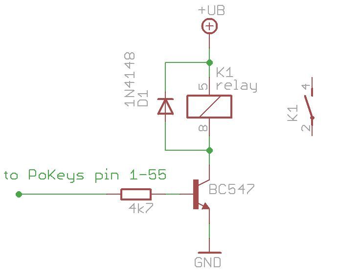
Quoting an expert on the Pokeys card "You can connect a relais to PoKeys via a simple circuit as shown below. PoKeys cards are recognized by ProSim.
If you use a BC547 transistor, make sure the relais does not take more then 100 mA. " (The Pokeys card outouts 100 mA per output so I believe this is the reason for the 100mA max draw as it might damage the Pokey card.)
Can you tell me if the 5v relay will draw more than 100mA and if it does, what can I do to ensure that it doesn’t draw more than 100mA? I’m a novice in electronics but guessing a resistor perhaps?
I may use the Maestro yet as I dabbled around with servo code so have a vague idea how to set that up on a time delay. My reason for wanting to use the Pokeys I/O card is that I wanted to use software offsets to activate the relay. I’m attaching a circiut that I would be using with the Pokeys card to give you an idea of what I want to use.
I made an error in my last post. After reading the Pokeys manual i’ve found the following
Quote "Digital output
Any one of the 55 pins can be configured as digital output by selecting ‘Digital output’ option box.
Each pin can sink or source up to 4 mA of current, with the limitation that the pins combined source
or sink current does not exceed 100 mA.
Ed
Like the circuit in the schematic you provided, our relay carrier boards have a transistor on board to drive the coil in the relay, so it seems like you should be able to connect the output of your device directly to the relay board. The current drawn by the enable pins should be well below 1 mA.
Thanks for all your information. I will be ordering several relays shortly. I have just one final question. I hope You mentioned the relay has a transistor on board already. Does it also have a diode and resistor on board ? If not would the same value components listed in the schematic (resistor and diode) be ok to use with the relay card?
Thanks much again,
Ed
EDIT: I found the schematic of the relay. It looks like there is a full circuit that matches or exceeds the circuit that I posted. I think I will be able to go directly from my I/O card to the relay without adding a circuit like the one I included in an above post. I notice several diodes and several 4.7 k resistors . It looks like the transistor is BSS138 . It doesn’t have the type of transistor symbol I’m normally use to as per the diagram I sent in earlier post but I’m hoping it will work fine.
The transistor on our relay carrier board is a MOSFET and the one used in your schematic is a BJT. The BJTs require a resistor in series with the “base” pin to limit the current drawn from the controller, where the “gate” pin on MOSFETs can be controlled using low amounts of current without this resistor, so long as the voltage across the gate and the source pins is high enough to enable the device (>2.5V). So, you should be able to connect the output pins of your device directly to the enable pins on the relay carrier.

 You mentioned the relay has a transistor on board already. Does it also have a diode and resistor on board ? If not would the same value components listed in the schematic (resistor and diode) be ok to use with the relay card?