I have the zumo shield connect to the arduino. I have succesfully controlled the motors and the buzzer of the zumo robot with the arduino so the board is getting proper voltage.
I am running the “serial” example sketch from the library. The magnometer readings seem to work (they change when I rotate the robot), but the accelerometer readings do not change, always reading “-32760”
I am sorry you are having trouble reading the accelerometer on the Zumo. Can you tell me more about your setup? Have you modified the serial sketch at all? Have you modified anything on the Zumo, or connected anything additional to it?
Also, what kind of Arduino are you using? Do you have another one to test the LSM303D with?
I am using a bluetooth shield that for some reason doesn’t connect SDA, SCL, and IOREF to the arduino. I connected the SDA and SCL lines to the arduino with some bits of wire, but had not connected the IOREF pin.
I have now connected the IOREF pin, and the Accelerometer works as expected. I did not know that the IOREF pin was needed for I2C (this is my first time working with I2C). Learn something new every day.
Sorry for wasting your time!
-Anderfreeb
EDIT 11/20/14 2240 EST (-5 GMT):
Actually the problem is intermitent. Seems to happen at random times. I think I may have a loose connection or a short somewhere. Not sure if connecting IOREF helped at all or if it just moved something somewhere else on the robot
I do not expect connecting your Bluetooth shield’s IOREF pin to improve communication with the Zumo’s LSM303D. Can you try removing the Bluetooth shield and all other I2C devices from your system and just try interfacing with the LSM303D and see if you get the same behavior?
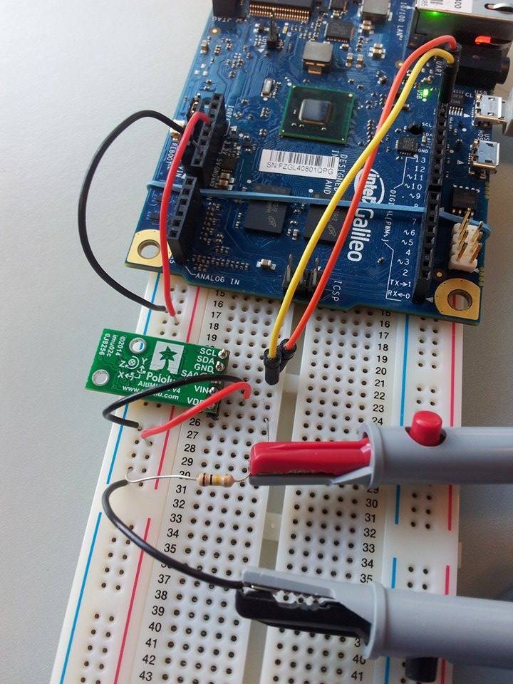
I have the same problem as above. The output from the LSD303D accelerometer on all three axis’s is always -32760, while the other component seem to be working fine. I am using an Intel Galileo gen 1 with the AltIMU-10 v4 PCB board. The VIN is connected to 5V (green wire), GND to GND on the board (blue wire), SCL to SCL on the board (orange wire) and SDA to SDA (yellow wire). The set up had been working fine beforehand.
I have tried changing the wires, the COM address, the section of the breadboard, numerous resets and restarting the computer. I don’t understand where the problem is when the gyroscope, magnetometer and altimeter all appear to be working okay. I am 99% certain that the gyro is working properly, less sure about the other components. The problem occurred as far as I can tell randomly… there was no changing of wires, rough handling or anything that of that nature.
The code I am using is:
#include <Wire.h>
#include <LSM303.h>

LSM303 compass;

char report[80];

void setup(){
  Serial.begin(9600);
  Wire.begin();
  compass.init();
  compass.enableDefault();
}

void loop()
{
  compass.read();

  snprintf(report, sizeof(report), "A: %6d %6d %6d    M: %6d %6d %6d",
    compass.a.x, compass.a.y, compass.a.z,
    compass.m.x, compass.m.y, compass.m.z);//Just to see that the magnetometer is okay
  Serial.println(report);

  delay(100);
}
I hope it didn’t get damaged by an electrostatic discharge or something… I’m really at my wits end here. Please help!
I am sorry you are having trouble with the accelerometer on your AltIMU-10. Do you know if anything changed in your system between the time when the IMU was working and when it stopped working?
When we were testing the accelerometer on the LSM303, we noticed we could get a similar behavior where the accelerometer constantly reported a single value for all axes. It seems that if you interrupt power to the accelerometer in a certain way (like disconnecting or turning off/on power) so that the voltage falls below a certain amount but not all the way to 0, then it can brown out and get stuck in a bad state. I’m not entirely sure that your case is similar, but our solution was to turn off all power and wait for at least 5 seconds to make sure the VDD voltage has dropped. You can measure it with a multimeter/oscilloscope to make sure the voltage has dropped completely to 0. If this turns out to be the problem, you can try adding a resistor (1k-10k) across VDD to ensure it goes low quickly when power is removed.
To the best of my knowledge the system did not change from before it stopped working. I am unaware of any alternative form of disconnect that may have caused a bad interrupt. The Galileo has a poorly documented limitation that when powering down the micro USB cable should be unplugged before removing the 5V jack. It was a while before I discovered that, and leaving the USB cable plugged in had not caused any problems previously. I still switched to unplugging it before powering off. Unless I did it the old way by accident, which still doesn’t make sense as I had been messing around for 2 weeks before I found that out!
I tired using a pull down resistor on VDD, the setup is shown attached. I’m more a software guy but I think what I did is what you suggested. I tried a 10kΩ resistor, and approx 1kΩ. Both times I tried varying VIN between 5V and 3.3V. In all cases VDD measured 3.31V.
I also tried applying 3.3V to VDD instead of VIN to no avail. Is there anyway to check if the device has been damaged?
It sounds like you implemented the pull-down the right way. Did you specifically power down, wait for at least 5 seconds, and measure the VDD voltage to make sure the voltage dropped?
If so, I am not entirely sure what might have happened. If you email us with your order information, and refer to this thread, I might be able to help you out with a replacement.
The problem described above looks much like mine. I attached a MinIMU-9 v3 to the I2C port (port 5) of the BrickPi (see dexterindustries.com). I can read out the L3GD20H gyroscope and the LSM303D magnetometer. Only the LSM303D accelerometer gives constantly -32760 on all axis. Any hints based on the experience above?
After some further search on the internet I found out the problem is that the LSM303D is very prone to power glitches as Pololu already stated in the FAQ of this product.
Searching from there I suddenly realized that I used the MinIMU9 VDD to power it. I rewired it to use the VIN instead of VDD and the problem is now solved.
I hope my mistake in wiring the board helps others not to make the same mistake.
I am glad that you were able to get it working by switching to the VIN input. In general, we found the best approach to fixing that issue is, as I described above (and as the FAQ says), to either wait long enough to make sure the voltage on VDD has dropped or to add a resistor across VDD to ensure it goes low quickly when power is removed.