I am trying to get a “Ultrasonic Ranging Module HC - SR04” working with the 3pi. A friend gave it to me saying it might be defective, and so far it is not working… I don’t know if it’s my programming, wiring, or the device itself that’s causing issues. Basically I want to use the sonar module to do a kind of wall following thing like with the Sharp distance sensors.
The module has 4 pins: VCC, GND, TRIG and ECHO. Apparently TRIG is the pin used to send a start signal to the sonar module and ECHO reports the information back.
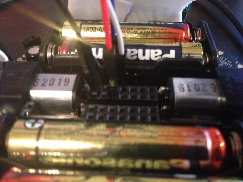
Here is my wiring (please don’t blast me if I am totally wrong on this):
I just connected the VCC & GND from the module to VCC & GND on the 3pi, and I connected TRIG to AD6 and ECHO to AD7 (I removed the appropriate jumper to free those I/Os).
As for the programming, I am pretty confused on what to do. I have read the documentation on the sonar module but it does not explain much (at least for me). I have tried using AD6 as a digital output and AD7 as a digital input, analog input and PWM input without any results.
This is the code that I last tried:
void initialize()
{
	pulse_in_start((unsigned char[]) {IO_D7}, 1);
	//set_analog_mode(MODE_8_BIT);
        while(!button_is_pressed(BUTTON_B));
        play_from_program_space(go);
        while(is_playing());
        delay_ms(200);

}


int main()
{
        // set up the 3pi
        initialize();

        // This is the "main loop" - it will run forever.

        while(1)
        {
        		set_digital_output(IO_D6, HIGH);
        		delay_us(10);
        		set_digital_output(IO_D6, LOW);
        		unsigned char newPulse = new_pulse(7);
        		if(newPulse)
        			set_motors(50,50);
        		delay_ms(500);
        		set_motors(0,0);
        		delay_ms(200);
        }

        // This part of the code is never reached.  A robot should
        // never reach the end of its program, or unpredictable behavior
        // will result as random code starts getting executed.  If you
        // really want to stop all actions at some point, set your motors
        // to 0,0 and run the following command to loop forever:
        //
        // while(1);
}
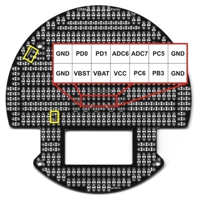
There are a couple of problems with what you’re doing. The first is your choice of ADC6 and ADC7 as pins to use. These two pins are dedicated analog inputs and cannot be used as digital inputs or outputs. Also, these pins are not the same as PD6 and PD7, which are digital pins assigned to hardware on the 3pi. Secondly, you aren’t using the PulseIn library quite right. Before complicating things with the pulse-in library, lets just test it out with simpler code so you can see if the sensor even works.
I suggest you connect pin PD1 to TRIG and pin PD0 to ECHO. Can you then try the following (untested) code and let me know what happens? What I hope it does is take one reading every second and print the results to the LCD (both in units of microseconds and inches).
int main()
{
  set_digital_output(IO_D1, LOW);  // make trigger pin low
  delay_ms(100);  // give the sensor time to start up

  while (1)  // main loop (loop forever)
  {
    clear(); // clear the LCD
    print("TRIG");  // print to the LCD
    set_digital_output(IO_D1, HIGH);  // make a 10 us pulse on TRIG
    delay_us(10);
    set_digital_output(IO_D1, LOW);

    while (!is_digital_input_high(IO_D0));  // wait until pin PD0 goes high (start of echo pulse)
    unsigned long ticks = get_ticks();  // get the current system time in ticks
    while (is_digital_input_high(IO_D0));  // wait until pin PD0 goes low (end of echo pulse)
    ticks = get_ticks() - ticks;  // length of the echo pulse in ticks (units are 0.4 us)

    clear();  // clear LCD
    print_unsigned_long(ticks*4/10);  // print echo pulse length in us
    print("us");
    lcd_goto_xy(0, 1);  // got to start of second LCD row
    print_unsigned_long(ticks*4/(10*148)); // convert pulse to inches
    print(" in");

    delay_ms(1000);  // wait for 1 second
  }
}
Also, thank you for posting a picture of your wiring; I really appreciate your taking the time to do that. Basically, your post is a perfect example of how to ask for help with a problem!
Thanks for your compliment on my post Anyway, I tried what you suggested and connected TRIG to PD1 and ECHO to PD0, then I loaded the code you supplied onto the robot. I did not see any readings next to “TRIG” on the screen; just a blank space… So I am assuming the unit is in fact defective. Oh well, it was worth a try. Thanks for your help Ben! I certainly appreciate it.
I wouldn’t jump to that conclusion quite yet; my code could very well have a bug, or there could be a connection issue. Do you have access to an oscilloscope? Can you post a picture of your new connections? One good change to try is implementing timeouts on the while loops that are waiting for the echo pulse so that you can’t get stuck in those forever. Is that something you would be able to do?
I think it’s probably easiest at this point if you look at what’s happening with an oscilloscope. You can simplify the program quite a bit to something like:
int main()
{
  set_digital_output(IO_D1, LOW);  // make trigger pin low
  set_digital_input(IO_D0, HIGH_IMPEDANCE);  // make ECHO a floating input
  delay_ms(100);  // give the sensor time to start up

  while (1)  // main loop (loop forever)
  {
    set_digital_output(IO_D1, HIGH);  // make trigger pin high
    delay_us(10);
    set_digital_output(IO_D1, LOW);  // make trigger pin low
    delay_ms(100);
  }
}
Can you look at the trigger pin with the scope to make sure it’s producing a 10 us pulse every 100 ms? Then can you look at the echo pin with the scope to see if it is doing anything?
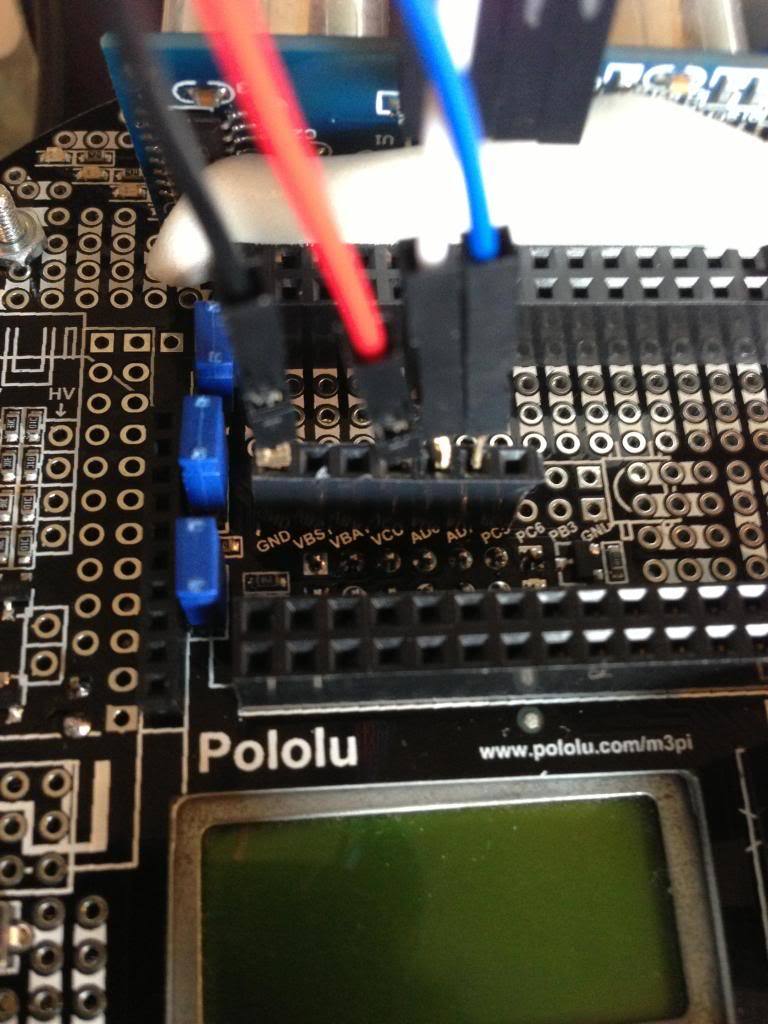
Also, thank you for the picture. However, I cannot tell where the white and blue wires are connected, and it looks like you have the red wire going to VBAT rather than VCC. Just to be clear, are all of your connections being made to soldered headers?
I’ll get my oscilloscope later on today then and I’ll implement the simplified code.
ECHO is going to PD0 and TRIG is going to PD1. My red wire is going to the socket after VBAT, which is VCC, or so it seems. The row labels look like “GND, VBAT, VCC, …etc” and I do have the red wire on the 3rd socket. And yes, all the wires are making connections to soldered headers.
Ok so I do have everything connected properly now… GND to GND, VCC to VCC (4th pin not 3rd), TRIG to PD1 and ECHO to PD0.
I checked both TRIG and ECHO with my oscilloscope and I only saw activity from TRIG. TRIG was sending the 10us pulse every 100ms, so no problems there. When I hooked the probe on ECHO, however, nothing was going on. The LCD keeps showing “0in” as the conversion too, which makes me think there’s no signal coming in and hence no values to convert, thus printing out 0 to the screen.
Not sure if you’re still working on SR04. This site may help in testing the SR04 to see if good. http://code.google.com/p/arduino-new-ping/. I downloaded and successfully used the code sample on my Arduino Uno.
Gary

 Anyway, I tried what you suggested and connected TRIG to PD1 and ECHO to PD0, then I loaded the code you supplied onto the robot. I did not see any readings next to “TRIG” on the screen; just a blank space… So I am assuming the unit is in fact defective. Oh well, it was worth a try. Thanks for your help Ben! I certainly appreciate it.