Here’s the skinny on my Zumo build:
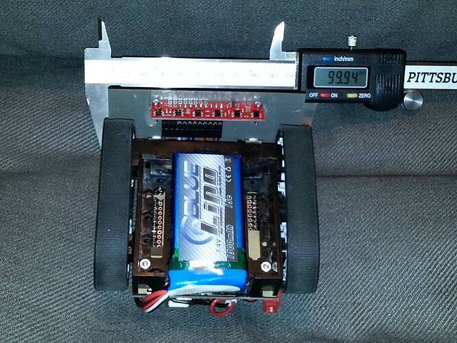
From the bottom:
You can see that I Dremeled out a space for the too-long LiPo battery pack, but even so, the motors are actually a smidgen too close together to fit the pack between them. The battery pack sticks out in the back.
The red strip is the 6-sensor part of the QTR-8RC. I was going to machine some mounts to screw them into the blade, but events have conspired against me (latest: brakes on my care broke down today!) so I gave up and used hot glue “for now” (yeah, that’s what I tell myself everytime ![]()
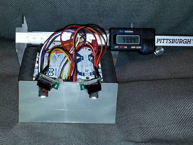
Here’s from the front:
The sensors are 10cm Sharp presence sensors. They can be used to either hug walls in navigation (slow down the tread opposed to the sensor which detects something) or to turn/ram into opponents for Sumo. It is kind-of near-sighted, though ![]()
Again, I had been designing a simple mount to screw the sensors into, but gave up and hot glued the screws. Hot glue does not stick very well to stainless, unless you really rough it up before, which I haven’t. Yet?
You also see the Scotch tape across the back of the sensors. This is to avoid the back of the sensor boards shorting out on the shield or other metal. Learned this the hard way ![]()
Right behind/below the sensors, you can see red and black wiring. That’s actually the wires for the motors. I pulled them up in front of the board and attached them to 90-degree headers on the shield, to be able to easily disconnect them and disassemble the robot again.
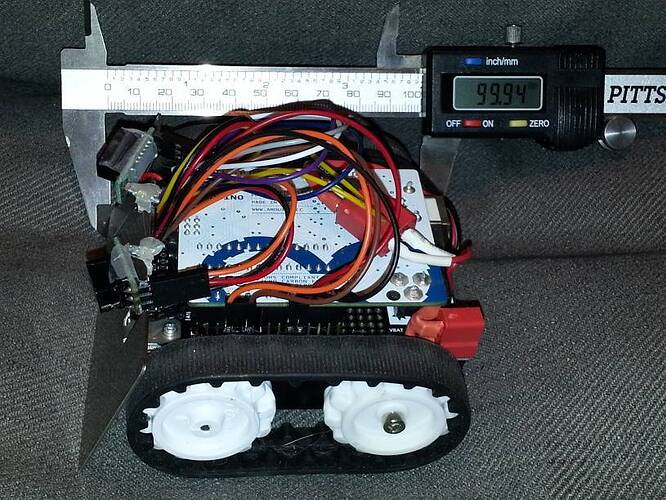
From the side:
Those silicone treads are dust magnets in my house, what with kids and cats and dogs and stuff.
You can also see that the LiPo pack is slightly too long – that’s actually just the wires and wrapping that protrudes beyond 100 mm, so it could be squished into a 100x100 millimeter cube. If this was designed, though, I’d go with a 900 mAh pack that probably would fit within the battery compartment, no Dremeling needed.
The red connectors are Deans-knockoff nylon-housed high-power connectors, which I use for all my batteries/motors. A little overkill, but so far, I have weight to spare if I’m designing to the 100mm division. I’ll probably have to add some steel bar on the inside of that battery compartment to make it heavier and stickier ![]()
The extra connector is for charging, and the LiPo balancing wire can be seen tucked in behind the unused USB port on the Arduino.
The rat’s nest of cabling on top is 6" pre-crimped female/female wiring connecting the sensors and the shield. I soldered extra male headers on the outside of the Arduino hook-up pins, which gives me access to all the signals both for sensors, and for debugging.
Right now, I’m not using A3, and also not using A4/A5 because I have nothing with I2C right now (not currently using the compass/accelerometer.) Possible future improvements include using the accelerometer to detect permanent angling (loss.) I could also use a second AVR controller with a LCD display and a few buttons to add a detachable configuration/debug UI over I2C.
Not visible, but also a mod: I de-soldered the R10 resistor from the shield, turning the 3:2 voltage divider into a 2:1 divider, which allows me to monitor the full range of the LiPo cell voltage. When the voltage goes below 6.55V, I make it stop the motors and start beeping like an alarm clock buzzer, to avoid draining down to 6.4V. It goes out of alarm mode if voltage recovers above 6.8V. I need a fair bit of hysteresis, because stopping the motors will make the voltage recover somewhat by itself.


