I’m trying to do a SPI communication between arduino mini pro and UM6-LT sensor.
UART communciation worked out fine, but I’m having a trouble using the SPI.
Below is one of the sample codes I tried, which is supposed to read the quaternion values from the UM6, but all that I receive from the sensor is just 255s (full bytes of 1). I checked the signals with oscilloscope, and the SS, SCK, MOSI signal from arduino were all idle, but the MISO signal from the UM6 was a constant value of 3.3V.
If you’re not seeing anything happen on SS, SCK, and MOSI, that suggests there’s something wrong with either your code or your wiring. Can you show us a picture or diagram showing how you have the UM6-LT connected to your Arduino?
I noticed you aren’t configuring the SS pin as an output with pinMode(), which I think you need to do (see the example code here).
I think I used the wrong word; I meant to say ideal, not idle. The signal from arduino is fine.
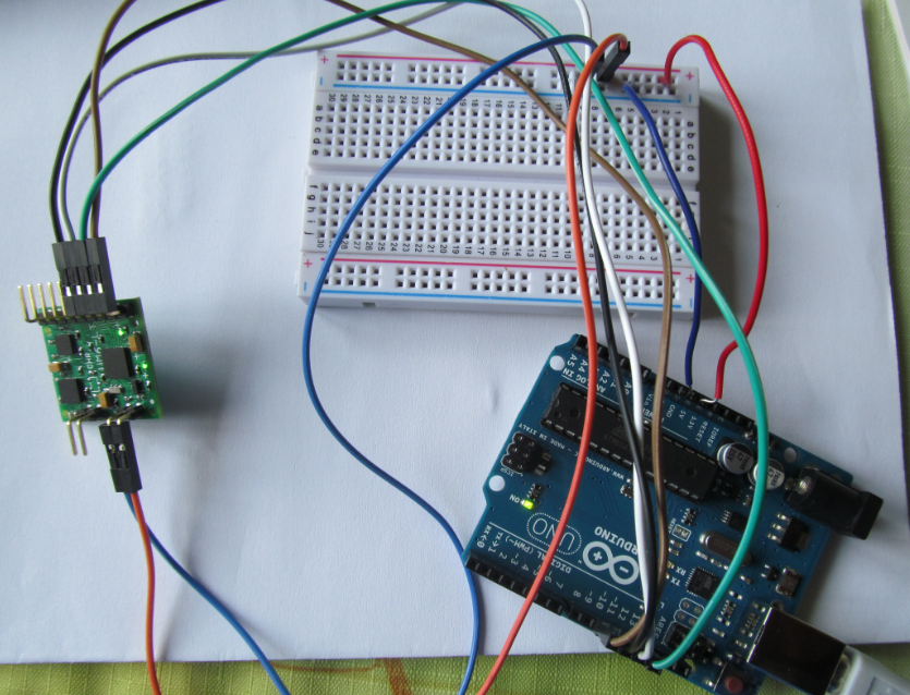
The connectino between arduino and UM6 are like below :
Arduino UM6
10(SS) - 9(SS)
13(SCK) - 8(SCK)
11(MOSI) - 6(MOSI)
12(MISO) - 7(MISO)
2(RX) - 1(TX)
3(TX) - 2(RX)
The RX and TX on arduino are Software Serials, Vcc’s are all connected to 5V, and GND’s are all connected to GND. For the SPI signals, I tried both using 5V directly from the arduino, and 3.3V by changing the signal from arduino.
I added the line pinMode(ss, OUTPUT); as you suggested, but still I’m getting the same result.
I don’t think I see anything else wrong with your connections or code. Unfortunately, I’m not sure why SPI communication isn’t working for you. I suggest you try contacting CH Robotics (the manufacturer of the UM6) directly, as they would probably be able to better help you figure out the problem.
If you do find a solution, we would be interested to hear about it.
I tried contacting the manufacturer, but couldn’t solve my problem. Meanwhile, I used the oscilloscope to check the SPI signals sending to UM6, and I found a small time gap (.5us, 1/8 of the clk cycle) between the bytes.
The SPI seems to have a small delay or gap between bytes to load the data to the register. I don’t think that it is sending wrong data to UM6, but would the gap actually matter on the communication?
Kyuwon,
I have seen a number of posts similar to yours on both this forum, Arduino forums, and elsewhere. I myself am struggling with EXACTLY the same issue you are (Although I am using a 3.3v ChipKIT).
I believe that the SPI implementation from CH Robotics has a bug, because I have literally not found ANYONE who can get this interface to work correctly, no matter what microcontroller or code they are using to connect to the device. This is unfortunate, because the UM6 is very unique in offering an SPI interface at all (FAR superior to an asynchronous serial for most applications). I think that CH Robotics will have to get their act together to fix this problem before this device sees wider adoption.
-Edit
I would note that these problems are true even with the latest firmware revision from CH Robotics (UM2B). Their datasheet states that previous versions do not support the SPI interface at all.
There is nothing wrong with the UM6 SPI hardware or firmware. Many of our customers have successfully connected to the the UM6 via the SPI bus. It is likely that you don’t hear about it because people don’t get online to complain about not having communication issues. However, in a previous version of the datasheet, the SPI mode was listed incorrectly. The correct SPI mode is mode 0. The most recent version of the datasheet has corrected this issue.
There are also a handful of common problems that you should check.
Make sure that the clock phase and polarity are correct. This is an amazingly common problem (even with correct documentation, some often don’t bother to check)
Make sure that all connections are correct. The SPI connections are simple enough, but people often forget to connect the communication grounds. If your device and the UM6 don’t share a common ground, THE BUS WON’T WORK.
Make sure your clock frequency is 400 kHz or below
Make sure that the slave select line remains low for the duration of the ENTIRE transfer during a SPI operation. Often, pre-written SPI libraries that write or read single bytes at a time do not leave the slave select line asserted between individual bytes.
If you are using a 5V logic level device to communicate with the UM6, the 3.3V TTL logic level of the UM6 may not be high enough to register as a logic high on your device. This will naturally cause communication to fail.
To initiate a command over the SPI bus, initiate a WRITE to the command register, not a read. This is in contrast to how you initiate a command over the serial port. Writing to address 0xAA (the GET_FW_VERSION command) will cause the firmware revision to be sent in the next four byte transfers over the MISO line.
We do test the SPI bus on all our devices before they ship, and they work. If you try the above and still can’t get it to work, there is a possibility that the hardware itself has failed (via an ESD event or a manufacturing defect). Please contact me at calebc@chrobotics.com and I’ll help you out.
3dogpottery @ Parallax forums has successfully established communication with the UM6 via SPI. He wrote the code in Assembly language I believe, so if someone would be so kind to convert this into an Arduino compatible language for a newb like me, that would be GREAT!
Thanks 3dogpottery for your hard work! UM6_SPI_Asm.txt (12.1 KB)
I have a question regarding UM6 communication via SPI bus. After challenging some code in Arduino IDE I still obtain rubbish values from UM6.
I wonder if You have working C code for this sensor? I know that above is .txt file containing Assembler code, but I’m not common with it and I have little to say what’s going on there.
I think that it may be a problem with hardware (UM6), but it’s not certain.
I am sorry you are having trouble communicating with the UM6. Can you tell me more about your setup? How are you supplying power to the UM6? Can you reduce your Arduino sketch to the simplest version that you think should work, but doesn’t, and post it? Can you also post pictures that show your connections?
Separately, have you tried connecting the UM6 to your computer and running the CH Robotics Serial Interface to see if the module is working? You can find the interface under the Resources tab of the UM6’s product page.
I did not notice anything obviously wrong with your code or setup. Have you tried connecting the UM6 to your computer and running the CH Robotics Serial Interface to see if the module is working? In general, verifying that your board is even working is a good first step to continue troubleshooting.
Also, Caleb from CH Robotics, the manufacturer of the UM6, posted his email address above ( calebc@chrobotics.com ), so you should probably contact him for help.
One possible problem in your code is that in your readRegister() function, the line digitalWrite(SPI_SS, HIGH); is at the very end. However, execution will not ever reach that line because the function will have already returned before that. You should try moving that line to right after the last SPI transfer (for hold3).

 However, in a previous version of the datasheet, the SPI mode was listed incorrectly. The correct SPI mode is mode 0. The most recent version of the datasheet has corrected this issue.