
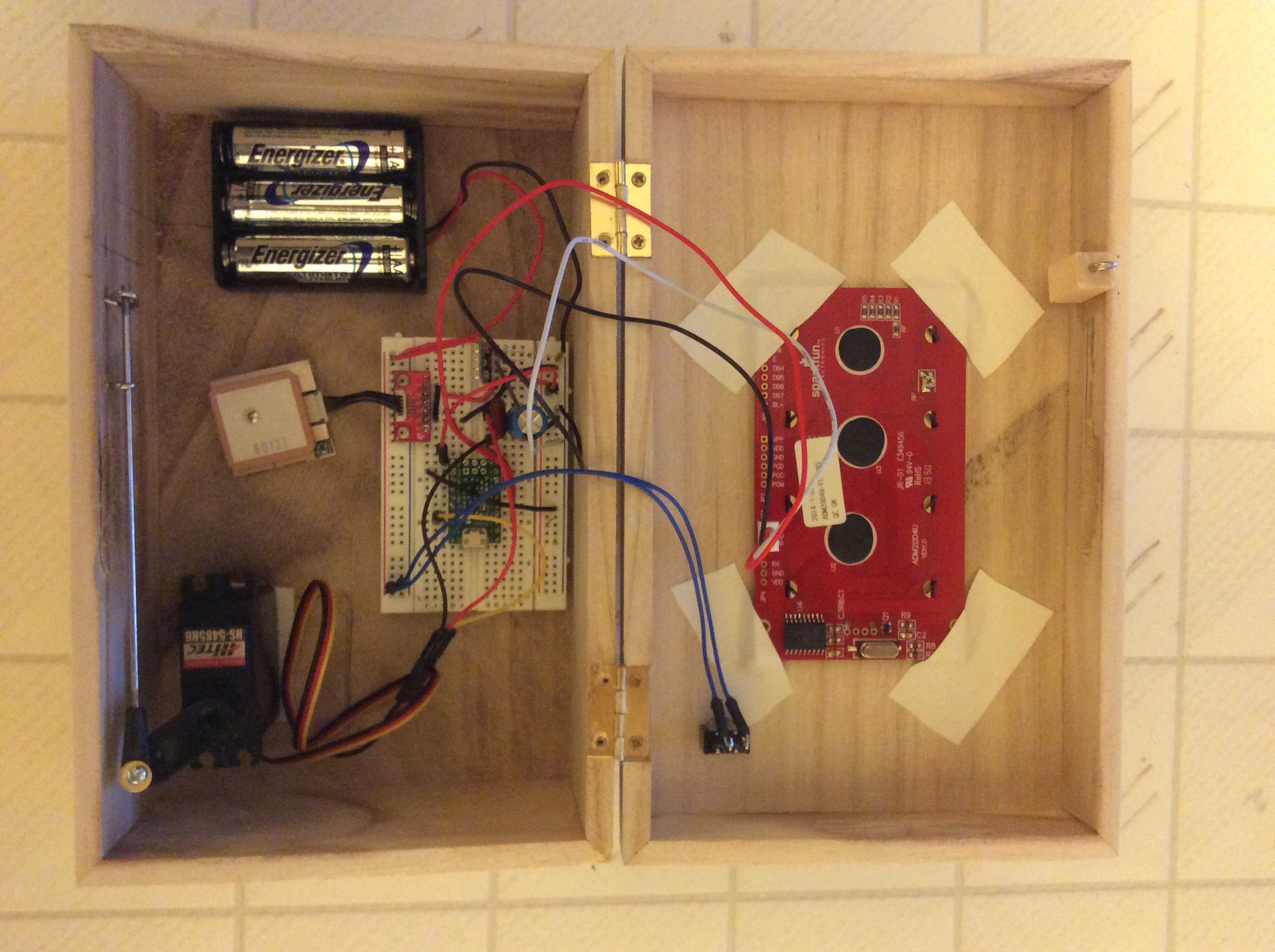
Note added on Nov. 28, 2014: I have built version 2 of the box. The circuitry
is now built into the bottom of the lid of the box, and I have added a Micro SD card
reader to the circuit. The Micro SD card allows a user to enter the location at
which the box will open, the distance tolerance, and a 20 character name of
the location into a file on the card. The box can be turned into a puzzle by
setting the name of the location to, for example, “Go To ???”.
Now there is plenty of room to put a gift in the box.
If someone is interested in version 2, post a reply and I will post the details,
including a schematic diagram of the circuit, which has become more complicated.
Writeup for version 1:
I designed this box based on Mikal Hart’s “Reverse Geocache Puzzle Box”
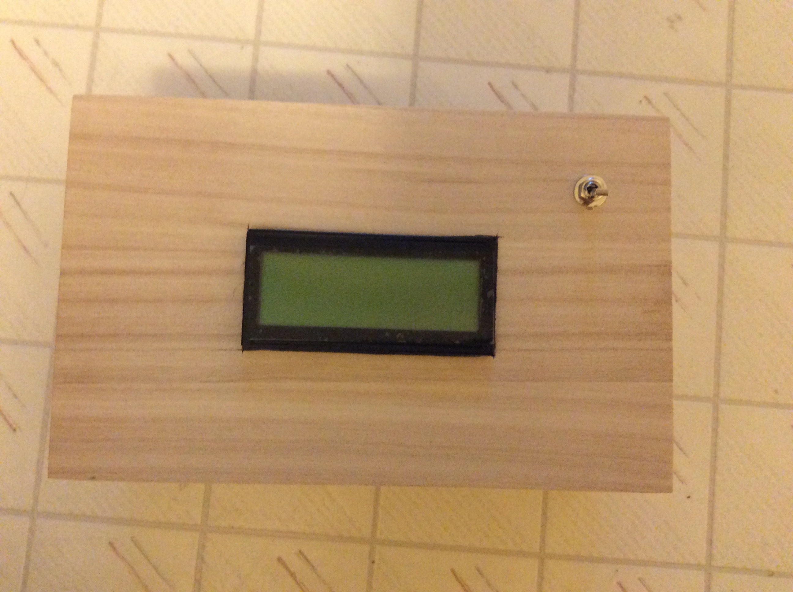
(MAKE magazine, Volume 25 Pages 144-145). My box is different from
his in that my box displays the location at which it will open and will
automatically unlock itself when you take it to that location.
The box uses an A-Star 32U4 Micro controller and I wrote the program
code myself, partly so I could totally understand what the code does
and how it does it. Hopefully, others will find it easy to understand also.
The code is completely self-contained and does not make use of any of
the GPS libraries that are available on the internet.
Photos
This is version 1 of the box. In the next version I’ll mount the components
in the lid of the box and make the wiring a lot neater.
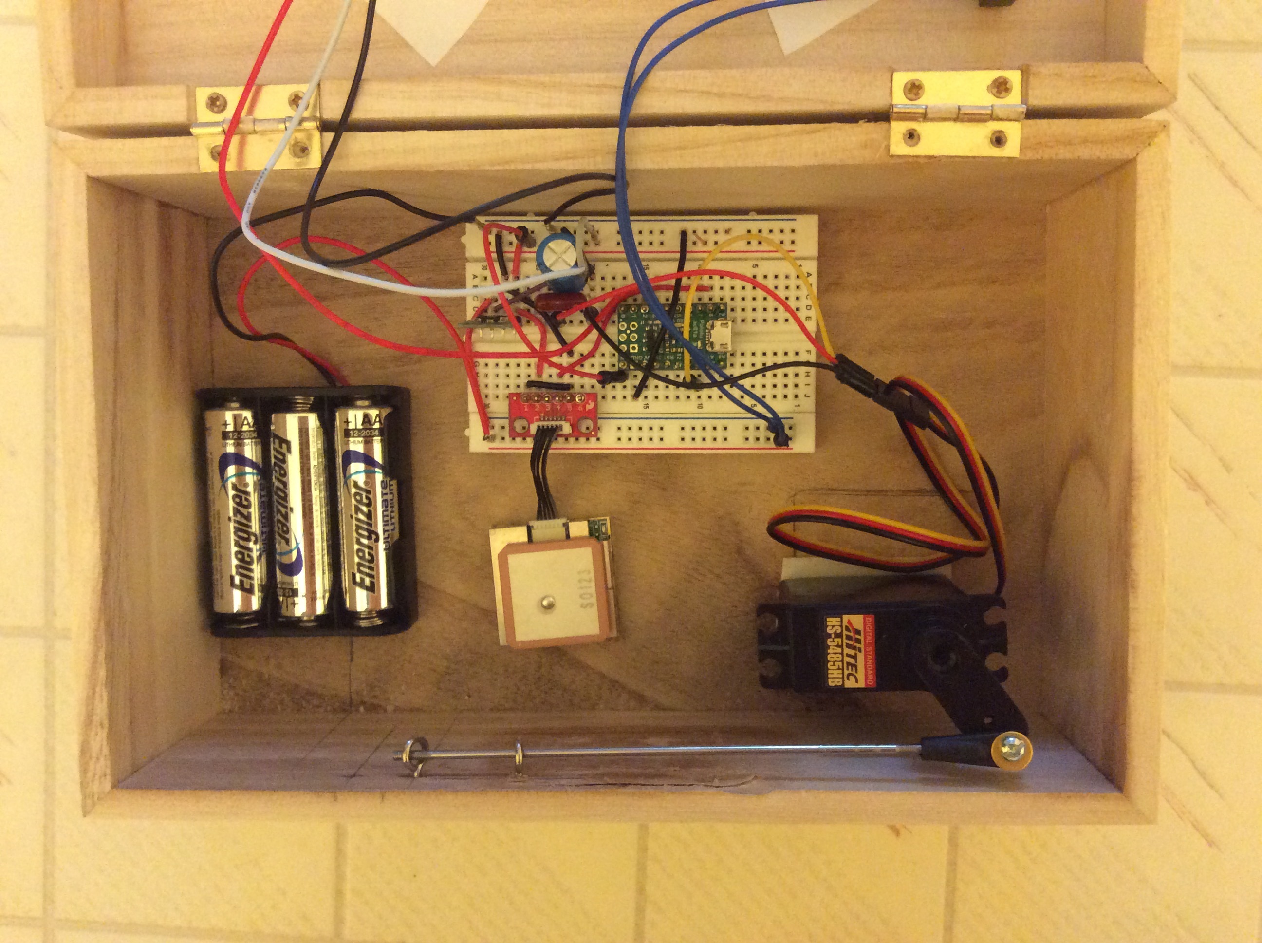
Parts
- USGlobalSat EM-506 GPS Receiver (Sparkfun #GPS-12751) - $39.95
- Pololu A-Star 32U4 Micro microcontroller (Pololu #3101) - $12.75
- Sparkfun Serial Enabled 20x4 LCD Black on Green 5V lcd display
(Sparkfun #LCD-09568) - $29.95 - Pololu 5V Step-Up/Step-Down voltage regulator (Pololu #2123) - $5.95
- 470 MFD, 35VDC Capacitor (RadioShack #272-1030) - $1.49
- Hitec 35485S HS-5485HB Digital Servo (Amazon) - 21.68
- ALIGN H70067 Servo Linkage Rod (Amazon) - $10.99
- Servo arm (scrounged from another servo)
- Basswood Box, 8.5" L, 5.25" W, 3.5" H (Michaels crafts) - $4.99
- SPST Flatted Metal Lever Toggle Switch (RadioShack #275-634) - $3.49
- Sparkfun GPS breakout board (Sparkfun #BOB-11818) - $3.95
- Pololu 3-Pin Female JST PH-Style Cable (Pololu #117) - $0.99
- Pololu 3-AA Battery Holder (Pololu #142) - $0.99
- Energizer AA Lithium Batteries 4 count (Amazon) - $8.20
- 1/2 inch screw eyes (Home Depot, Everbilt #216) - $2.36
- Breadboard (Sparkfun #PRT-12002) - $4.95
Connections
Since most of the electronic parts don’t have symbols for schematic
diagrams, I will simply list the connections.
-
The ground connection (GND) is common to all of the electronic
parts. -
A-Star 32U4 Micro
> ground pin → GND.
> VIN pin → voltage regulator VOUT
> Pin 2 → LCD RX
> Pin 8 → GPS Pin 4
> Pin 10 → Servo yellow wire (signal wire) -
GPS Receiver
> Pin 1 → Pin 5 → GND
> Pin 2 → voltage regulator VOUT
> Pin 4 → A-Star pin 8 -
Servo
> Black → GND
> Red → battery +
> Yellow → A-Star pin 10
Note: If you connect the servo to VOUT of the voltage regulator,
the high instantaneous current draw of the servo might
overload the voltage regulator. The same goes for the
charging of the capacitor. -
Voltage Regulator
> GND → GND
> VIN → battery +
> VOUT → A-Star VIN → GPS pin 2 -
Capacitor
> Negative → Servo black
> Positive → Servo red -
Battery
> Negative → GND
> Positive → voltage regulator VIN
Arduino Program
/*
This software was written by Bob Day.
It was written in October, 2014.

This software is licensed under the terms of the Creative
Commons "Attribution Non-Commercial Share Alike" license, version
3.0, which grants the limited right to use or modify it NON-
COMMERCIALLY, so long as appropriate credit is given and
derivative works are licensed under the IDENTICAL TERMS.  For
license details see

  http://creativecommons.org/licenses/by-nc-sa/3.0/

This source code is distributed in the hope that it will be useful,
but WITHOUT ANY WARRANTY; without even the implied warranty of
MERCHANTABILITY or FITNESS FOR A PARTICULAR PURPOSE.

Note: Modify this program as you wish.  You'll definitely need to
define the longitude and latitude of the destination at which the
box will unlock, and the name of the destination in the LCD
greeting.
*/

#include <Servo.h>
#include <SoftwareSerial.h>
// #include <serial.h>

        // Pin assignments
static const int RX_from_GPS = 8;
static const int TX_to_LCD = 2;
static const int servo_control = 10;

        // These values should be adjusted according to your needs
static const int CLOSED_ANGLE = 90; // degrees
static const int OPEN_ANGLE = 60; // degrees
// static const float DEST_LATITUDE = 43.04025;   // Senior Center
// static const float DEST_LONGITUDE = -70.7859; //       "
// static const float DEST_LATITUDE = 43.09605;    // Coastal Fitness
// static const float DEST_LONGITUDE = -70.750967; //       "
static const float RADIUS = 1.0; // Miles.

        // Fixed values should not need changing
static const int DEF_ATTEMPT_MAX = 50;
// static const int EEPROM_OFFSET = 100;

        // The basic objects needed
SoftwareSerial GPS_serial(RX_from_GPS, 0);
SoftwareSerial LCD_serial(0, TX_to_LCD);
Servo servo;
float distance_miles = 1000000.0;
float latit = 0.0;
float longit = 0.0;
int   checksum;
int   idx; // Index variable.
int   len;
char  tempStr[16];
char  nmeaStr[128];
char  gpsChar = 0; // The incoming character from the gps.

// The Arduino setup() function
void setup()
{
pinMode(RX_from_GPS, INPUT);
pinMode(TX_to_LCD, OUTPUT);
pinMode(servo_control, OUTPUT);

memset(nmeaStr, 0, sizeof(nmeaStr)); // Clear the nmea sentence.

        // Attach the servo motor.
servo.attach(servo_control);

        // Establish a debug session with a host computer. // @@@@@ Debug
// Serial.begin(115200);

// while (!Serial) ; // Wait for Arduino Serial Monitor to open. // @@@@@ Debug

        // Establish communications with the GPS module.
GPS_serial.begin(4800);

        // Establish communications with the LCD display.
LCD_serial.begin(9600);
LCD_serial.listen();
delay(10); // Wait a little bit while the LCD starts booting.
LCD_serial.write(18); // Then, make sure it's at 9600 baud.
delay(2000); // Give the LCD time to finish booting.

        // Set the size of the display if it isn't 20x4
        // (You only have to do this once).
    // LCD_serial.write(0x7C);
    // LCD_serial.write(3); // 20 character lines.
    // LCD_serial.write(0xFE);
    // LCD_serial.write(5); // 4 lines.
    // delay(100);
        // Sparkfun suggests putting delays after each command to
        // make sure the data is sent and the LCD is updated.

        // Set the brightness - turn it off.
        // (You only have to do this once).
    // LCD_serial.write(0x7C);
    // LCD_serial.write(128);
    // delay(100);

        // Clear the display and display the initialization message.
LCD_serial.write(0xFE);
LCD_serial.write(0x01);
delay(10); // Sparkfun suggests putting delays after each command.
LCD_serial.write(0xFE); // Set the LCD cursor to the beginning of the first line.
LCD_serial.write(128); // 128 + 0.
delay(10);
LCD_serial.print("Starting up...");

        // make sure motorized latch is closed.
// delay(5000);
servo.write(CLOSED_ANGLE);
delay(500);

        // Greeting.
LCD_serial.write(0xFE); // Set the LCD cursor to the beginning of the first line.
LCD_serial.write(128); // 128 + 0.
delay(10);
// LCD_serial.print("Senior Center.");
// LCD_serial.print("Go to Coastal Fit.");

LCD_serial.write(0xFE); // Set the LCD to the second line.
LCD_serial.write(192); // 128 + 64.
delay(10);
LCD_serial.print("Seeking GPS fix...");
// delay(300000); // For now.
} // End of setup().

        // The Arduino loop() function
void loop()
{
GPS_serial.listen();
while (1)
  {
  if (GPS_serial.available() )
    {
    gpsChar = GPS_serial.read();
    // Serial.write(gpsChar);
    if (gpsChar == '$') // Find the beginning of an nmea sentence.
      {
      nmeaStr[0] = '$';
      for (idx = 0; idx < 127; ) // Get the sentence.
        {
        if (GPS_serial.available() )
          {
          gpsChar = GPS_serial.read();
          // Serial.write(gpsChar); // @@@@@ Debug
          nmeaStr[++idx] = gpsChar;
          if (gpsChar == '\n')
            break;
          }
        }

      nmeaStr[idx-1] = '\0'; // Terminate the sentence at the CR.
// Serial.print("Place 1. idx = ");  Serial.print(idx); Serial.println(nmeaStr); // @@@@@ Debug
      }
    else
      continue;  // continue the while (1) loop.

    if (idx < 128)
      {
      if (strncmp(nmeaStr, "$GPRMC", 6) == 0) // If it's a $GPRMC sentence,
        break; // leave the while (1) loop.
      else
        continue; // continue the while (1) loop.
      }
    } // End of if (GPS_serial.available() )
  } // End of the while (1) loop.

// Serial.print("Place 2. nmeaStr[18] = ");  Serial.println(nmeaStr[18]); // @@@@@ Debug

if (nmeaStr[18] == 'A') // If we have a valid fix...
  {
  LCD_serial.listen();
  LCD_serial.write(0xFE); // Set the LCD to the second line.
  LCD_serial.write(192); // 128 + 64.
  delay(10);
  LCD_serial.print("GPS fix obtained.   ");
  delay(1000); // Let the user see it.

  len = strlen(nmeaStr);
  checksum = Hex(nmeaStr[len - 2]) * 16;
  checksum += Hex(nmeaStr[len - 1]);
  for (idx = 1; idx < len - 3; ++idx)
    checksum ^= nmeaStr[idx];

// Serial.print("Place 3. checksum = "); Serial.println(checksum); // @@@@@ Debug

  if (checksum == 0) // If the checksum is OK...
    {
    // Get latitude and longitude.
    strncpy(tempStr, nmeaStr+20, 2); // Get latitude degrees.
    tempStr[2] = '\0';
    latit = atof(tempStr); // Convert to floating point.
    strncpy(tempStr, nmeaStr+22, 7); // Get latitude minutes.
    tempStr[7] = '\0';
    latit += atof(tempStr)/60.0; // Convert to floating point and add.
    if (nmeaStr[30] == 'S')
      latit = -latit;

    strncpy(tempStr, nmeaStr+32, 3); // Get longitude degrees.
    tempStr[3] = '\0';
    longit = atof(tempStr); // Convert to floating point.
    strncpy(tempStr, nmeaStr+35, 7); // Get longitude minutes.
    tempStr[7] = '\0';
    longit += atof(tempStr)/60.0; // Convert to floating point and add.
    if (nmeaStr[43] == 'W')
      longit = -longit;

    // Calculate the distance from the destination.
    distance_miles = Distance(longit, latit, DEST_LONGITUDE, DEST_LATITUDE);

// Serial.print("Place 4. latit = "); Serial.println(latit, 5); // @@@@@ Debug
// Serial.print("Place 4. longit = "); Serial.println(longit, 5); // @@@@@ Debug
// Serial.print("Place 4. distance_miles = "); Serial.println(distance_miles, 5); // @@@@@ Debug
// delay(3600000); // @@@@@ Debug

    // Are we close??
    LCD_serial.write(0xFE); // Set the LCD to the fourth line.
    LCD_serial.write(212); // 128 + 84.
    delay(10);
    if (distance_miles <= RADIUS)
      {
      servo.write(OPEN_ANGLE); // Open the box.
      delay(500);
      LCD_serial.print("The box is open! ");
      }
    else // Nope. Display the distance.
      {
      LCD_serial.print("Miles to go: ");
      LCD_serial.print(distance_miles, 1);
      servo.write(CLOSED_ANGLE);
      delay(500);
      }

    delay(3600000);
    } // End of "If the checksum is OK..."
  } // End of "If we have a valid fix..."
} // End of loop().

//
// Functions
//
// Read a hex character and return 0 to 15
byte Hex(char chr)
  {
  if (chr < '0')
    return 0;
  if (chr <= '9')
    return chr - '0';
  if (chr < 'A')
    return 0;
  if (chr <= 'F')
    return (chr - 'A') + 10;
  else
    return 0;
  }

// Calculates the geodesic distance in miles between
// two points specified by radian latitude/longitude using the Haversine formula (hf)
float Distance(float longit1, float latit1, float longit2, float latit2)
  {
  float cvt_radians = 3.141592654/180.0;
  float R;
  float dLongit;
  float dLatit;
  float a;
  float c;
  float d;

  R = 3956.5467; // Earth mean radius in miles. (Source: WolframAlpha).
  dLongit = (longit2 - longit1)*cvt_radians;
  dLatit = (latit2 - latit1)*cvt_radians;
  latit1 = latit1*cvt_radians;
  latit2 = latit2*cvt_radians;
  a = Square(sin(dLatit/2.0)) + cos(latit1) * cos(latit2) * Square(sin(dLongit/2.0));
  c = 2.0 * asin(min(1.0, sqrt(a)));
  d = R * c;
  return d; // Distance in miles.
  }

float Square(float value)
  {
  return (value * value);
  }