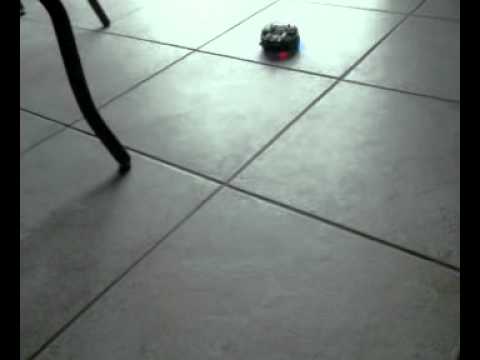
Here’s a link to a video of my sound-following 3pi robot.

Hardware:
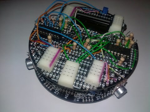
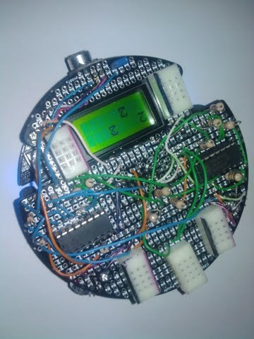
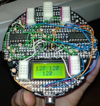
It basically just uses three of the SparkFun Electret Microphone Breakout Boards and two 74HC4052 multiplexers.
After reviewing the Pin assignments, and reading up on the 3pi in general, I decided that I really didn’t want to give up ADC6 since it monitors the battery voltage. Without having three ADC channels to connect to, adding a multiplexer seemed like the obvious choice, though it came at the cost of two IO lines. I chose PD0 and PD1 (which double as Serial Tx/Rx), since they weren’t being used for anything else.
While I was prototyping on my breadboard with a separate Atmega328, I found the serial Tx/Rx to be extremely valuable for debugging and soon realized that I would need to free up PD0 and PD1. My solution again was to add another mux/demux, but this time I only use one IO line to drive the selectors. PC5 is attached to S0 of Mux1, and S1 is pulled to ground. When PC5 is low (by default), my Tx/Rx lines are patched to a 3-Contact Point Block (special thanks to Jan for identifying these for me!). If I drive PC5 high, Tx/Rx are patched to the selectors of Mux2 to be used to select the analog input to sample.
In summary:
- 3 Electret BOBs connect to Mux2
- PD0 & PD1 connect to common I/O’s of Mux1
- PC5 is used as a selector for Mux1.
- When PC5 is low, PD0 & PD1 are used for serial I/O.
- When PC5 is high, PD0 & PD1 are used as selectors for Mux2
- ADC7 is used to sample analog output of Mux2.
Software:
The software basically loops 256 times in the main loop, sampling each of the three mics once per loop and storing the values in an array. The states of PD0 and PD1 are toggled to select which mic I want to sample. “00” = off, “01” = mic1, “10” = mic2, "11 = mic3. After the 256 loops, I analyze the data looking for the highest high, and the lowest low for each mic. The assumption here is that the highest amplitude (the diff b/w the highest high, and lowest low) is going to be registered on the mic nearest to or directed at the source of the sound. This isn’t perfect, but has proven to be reliable enough.
I’ve changed the algorithm a few times, but they are as follows:
(This algorithm is used in the video above)
- Are the amplitudes which have registered significant?
1a) If no, return to main loop. - Is the back mic significantly louder than the front mics?
2a) If yes, do a 180*, sleep, then return to the main loop. - Set the speed of the motor to a value roughly based on the amplitude of the opposite mic. ie, motor1 ~= MIC2, and motor2 ~= MIC1.
(New algorithm not yet video’d, but much better)
- Are the amplitudes significant?
- Is the back mic slightly louder than the front mics?
2a) If yes, do a 180*, sleep, return to main loop. - Is one front mic significantly louder than the other?
3a) If no, drive straight-ish, curving toward the loudest mic. Sleep. Return to main loop. - Which of the front mics is the loudest?
- Spin in the direction of the loudest Mic.
5a) Spin in degrees proportionate to the difference between the loudest mic and the 2nd loudest mic. ie, if 2nd loudest mic is almost just as loud, turn 120* (1/3 full circle) so both front mics straddle sound source. If the 2nd loudest mic is half as loud, it would turn half the distance. - Return to main loop to resume sampling, and hopefully to drive straight-ish now.
That’s basically it. I would love to get some feedback from others.
I have a couple of other applications for the hardware/software. Here are a couple ideas I have come up with. Let me know if you can think of more!
- Use the mics and an FFT algorithm to follow a certain frequency. IE, ignore background noise and only follow a whistle.
- Use the mics and an FFT algorithm to receive commands, either by whistle or DTMF. For instance, grid coordinates could be conveyed through DTMF.
- Marco Polo! I would like to get my robot to play “Marco Polo” with some other robots, or maybe even my Android phone. Basically, the 3pi would wander about and would sound it’s buzzer at a certain tone to indicate “Marco”. Other 3pis/robots/cell phones would respond with another tone meaning “Polo”. Using the three Mics and maybe FFT, the 3pi would home in on a player.
- Tease my dog - switch between sound following and sound avoidance to charge at her barks, then run away from them at intervals.

–Louie


