My Absurd Project – The One-Million-Color Flashlight!

Ok so this “project” is, admittedly, a bit silly, but it was fun to build and even more fun to program! A flashlight isn’t all that fancy compared to walking robots, and zippy line tracers, but I needed something I could build with the handful of test components I purchased that would let me test what I suspected would be a solid, sophisticated model for programming the Mini Maestro. The One-Million-Color Flashlight fit the bill, and so far, I’d say I’m on the right track with the code. I <3 the Maestro! :slight_smile:
So why One-Million colors? Because the ShiftBrite modules display a 10-Bit RGB spectrum (~ 1 billion colors), but the device changes color component values in steps of 10, and limits maximum intensity to 1000 (instead of 1023, or the max value of 10 bits). So the result is 1,000,000 color combinations rather than 1 Billion.

Operation was designed more around a code experiment than a user experience, but the device is still fairly simple to operate. Toggling the power switch to “On” activates the device and it initially emits “white” light (Red, Green, and Blue components at maximum intensity). The rear color component indicator illuminates red, meaning that the gauge needle is displaying the current Red color component value. A push button to the left of the color component indicator LED can be pressed and released to cycle through the three color components, causing the gauge to display each value in turn. Three push buttons, designated Red, Blue, and Green, by small plastic beads, can be pressed and held to decrement the intensity of the related color component. When a value reaches 0, it is reset to 1000. Finally, in the upper right, a smaller red LED and push button are provided as an “it should be working” button. This button and LED are wired straight to power and pressing the button should cause the light to come on whenever the regulator is powered and working.

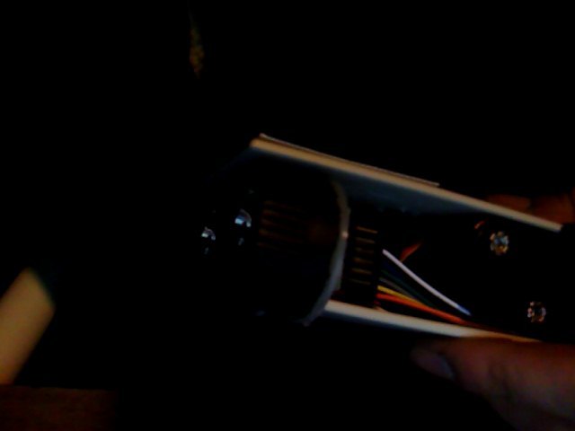
On to the physical device itself; here’s a top-down picture of the device on its side, with the beams pointed to the left:

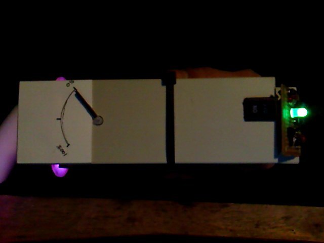
It’s not made of much; a couple of old 5-1/4" drive bay covers from a PC make up the base plate and top cover. There are no sides - just a top and bottom compressed around an eight-cell AA battery holster with cable ties. At the rear end of the battery holster (the right end, with the small green LED in the picture) the Mini Maestro 12 is mounted to the base plate by sliding its two mounting holes over two nylon screws, hot-glued upside-down to the base plate. Behind the Maestro sits the D15V35F5S3 power regulator, essentially suspended by its own 18 gauge wiring. Finally, a small RadioShack prototype PCB board, hot glued on its bottom edge to the base, houses the control interface (e.g. 5 push buttons and 2 indicator LEDs). A sturdy toggle switch was fitted into a notch cut into the top cover and hot-glued into place.

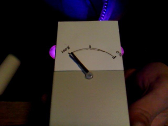
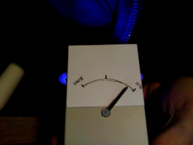
The left end (ahead of the battery pack) houses the two beam assemblies along with a servo which controls the needle of the color component intensity indicator gauge. You can see in the photo (sort of!) that the indicator needle is pointing to 0% intensity and the currently displayed color component is Green (the color of the rear LED). The Red and Blue components have high values, and so the light projected is purple in color.

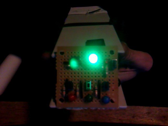
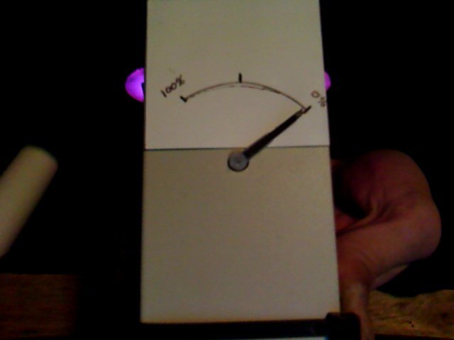
Here is closer view of the rear of the device, followed by a closer view of the gauge at the front of the device.

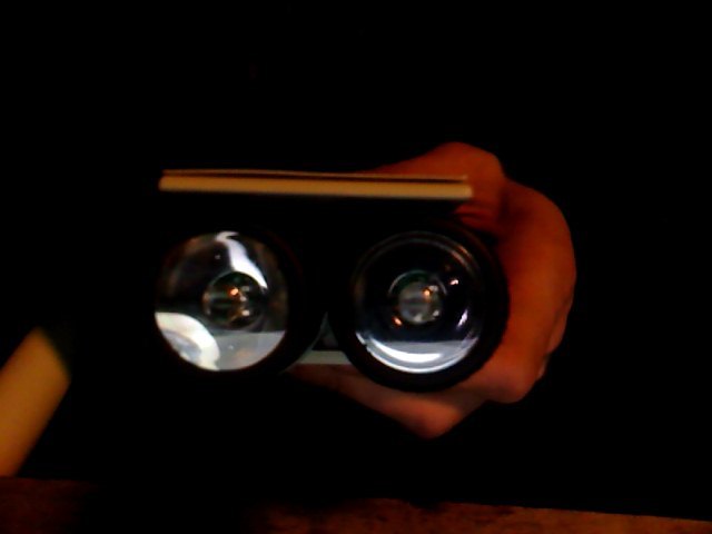
The beam assemblies are each constructed from a ShiftBrite module screwed to a nylon spacer via their PCB mounting holes. The nylon spacers are hot-glued to flashlight heads, modified for the purpose. The flashlights where originally $1.00 Rayovac all-plastic flashlights, but I used a Dremel to cut down the head to a much lower profile, and removed the mounting for the original incandescent lamp. The two spacers were then glued to another nylon fastener designed for mounting cable ties (a cable tie cradle mount) and the cable tie mount slides onto a post (modified to have its latch removed) on the 5-1/4” drive bay base plate. Here are a couple of images of the front beam assemblies (too bad the light cannot illuminate itself for the photos! Sorry!!)


The rear control panel, as described above, looks like this:

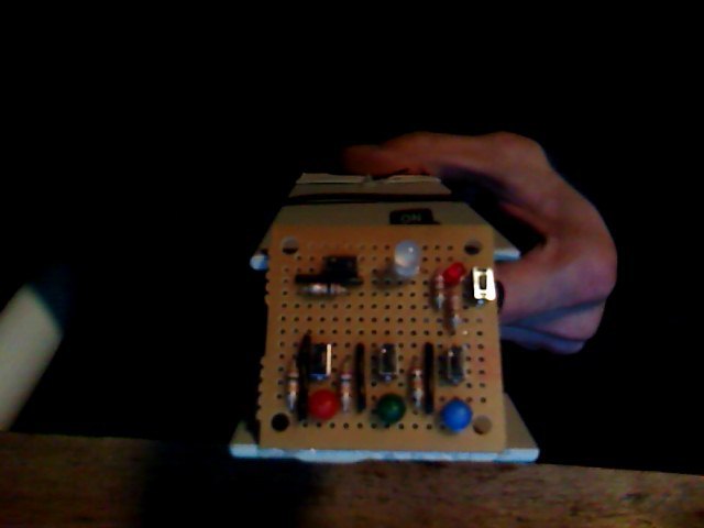
One thing to note is that the resistor to the left of the power monitor LED is an additional 220 Ohm on the Red channel of the indicator LED. This is to help compensate for the large difference in forward voltage between Red and the other two color leads. In this configuration, each color gets approximately 7 to 8 mA (which is still almost too bright for the application – I found this surprising as I expected the LED to possibly be too dim!).

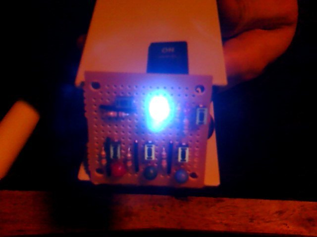
Here are some shots of the indicators in various states – notice that in the image of the Red indicator, the Red value has been set to 0 and the light has become quite blue.

As I said in the opening, this project was really about testing code designs for the Maestro. I really like the simple stack-based scripting and wanted to explore its potential. The basic idea was to create a variable list at the base of the stack and manipulate it as required to emulate the usage of standard code variables. I suspected that one could create structure layouts to even implement some very basic class-oriented design principles. As the variable usage has worked beautifully, I’m pretty sure that small structures, and subroutines to work with them, could be written to really expand the horizons of what the scripting can do.
Anyway, before looking at the code, here is a screen shot of the configuration in Control Center:

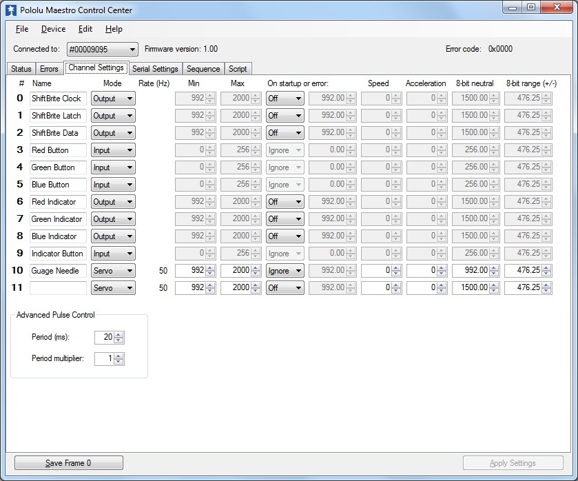
The configuration is a pretty simple set of inputs and outputs, and the labels should make it clear what each does (the Red, Green, and Blue Indicator channels each drive the respective pin of the multicolor LED).
The code was fun to work out, and wound up being simpler than I expected it to be. I’m really interested to start a more complex project now; one where I can ramp-up this model and find its limits. Anyway, the code consists of a main program loop which executes five primary steps. In addition, there is a slightly modified version of the Pololu-provided script for controlling ShiftBrite modules. The logic, and most of the code, is documented in comments so I’ll just post the code and if it doesn’t explain itself, you can feel free to ask questions.

# *************************************************************************
# RGB Flashlight
# For Pololu Mini Maestro
# v1.0 - 1/3/2011
# By Reed Kimble
# *************************************************************************

# Main Program Subroutine
Sub Main
 # Boot
 100 delay # Wait for device circuits to energize.

 # Initialize Variables
 1    # [000](Bool) Has desired color changed?
 3    # [001](Int ) Level Indicator Color; stack address of color component.
 1    # [002](Bool) Color Component Switch state.
 1000 # [003](Int ) Desired Red color component.
 1000 # [004](Int ) Desired Green color component.
 1000 # [005](Int ) Desired Blue color component.

 # Primary program loop - 5 steps:
 begin
  ########################################################################
  # [Step 1]
  #
  # Check the state of the color component mode switch.  When the switch
  # toggles from low back to high, increment the color variable value from
  # 3 to 6. This value is the memory address of the value of the selected
  # color component. If the value is 6 when incremented, it is wrapped 
  # back to 3 (the 7 is dropped).

  9 get_position # Check the state of the Indicator Button.
  if # If the button state is high, check to see if it was low previously...
    2 peek
    if else # If the indicator button variable was low, increment the value.
      1 peek
      1 plus
      dup 6 minus # Duplicate the incremented value, then subtract the max.
      if # If the result was not 0, the incremented value is saved to
        1 poke # the color variable.
      else
        drop 3 1 poke # If the result was 0, the incremented value is dropped
      endif           # and the color variable is reset to 3.
      1 2 poke # Set the button state variable back to high.
    endif
  else # If the button state is low, just set the state variable to 0.
    0 2 poke
  endif

  ########################################################################
  # [Step 2]
  #
  # Check the state of each color component button (Red, Green, and Blue)
  # and decrement the associated variable value if the button is pressed.

  3 get_position # Check the state of the Red button.
  if else # If the input is low (pressed)...
    rot # Get the Red variable value to work with.
    10 minus dup # Decrement the value, the duplicated it for a check.
    if else # If the value is 0, reset it to 1000
      drop 1000
    endif
    rot rot # Restore the variable order
    1 0 poke # Set the desired color changed variable to True
  endif

  # Repeat the above for the Green button and variable
  4 get_position
  if else
    swap
    10 minus dup
    if else
      drop 1000
    endif
    swap
    1 0 poke
  endif

  # Repeat for the Blue button and variable
  5 get_position
  if else
    # No need to manipulate the stack this time- Blue is on top.
    10 minus dup
    if else
      drop 1000
    endif
    1 0 poke
  endif

  ########################################################################
  # [Step 3]
  #
  # Check the color component indicator variable value for each color,
  # and set the multicolor indicator LED to the appropriate color.

  1 peek
  3 minus # Copy the indicator value and test it...
  if else # If the result is 0 then the value is the Red component register
    8000 6 servo # Turn on the Red lead of the indicator LED
    0 7 servo # Turn off the Green lead of the indicator LED
    0 8 servo # Turn off the Blue lead of the indicator LED
  endif

  1 peek  # Repeat test for Green register, set LED accordingly
  4 minus
  if else
    0 6 servo
    8000 7 servo
    0 8 servo
  endif

  1 peek  # Repeat test for Blue register, set LED accordingly
  5 minus
  if else
    0 6 servo
    0 7 servo
    8000 8 servo
  endif

  ########################################################################
  # [Step 4]
  #
  # Get the value of the selected color component (remember, this value
  # is a memory register location for the color component value).  Then
  # set the gauge servo to 4 times this value, plus 4000 (the value will
  # be between 0 and 1000 so this gives us a range between 4000 and 8000).

  1 peek peek  # Get the selected color register, then value at that register.
  4 times 4000 plus
  10 servo # Send the calculated value to channel 10 (the gauge servo).

  ########################################################################
  # [Step 5]
  #
  # If necessary (if a color component value was changed), update the
  # ShiftBrite modules.

  0 peek # Check the desired color changed variable value.
  if # If it is 1 (true) then copy the current color component values and
    3 peek  # call the rgb sub.
    4 peek
    5 peek
    rgb
  endif

  0 0 poke # Reset the desired color changed variable value.

 #########################################################################
 # Continue execution of the main program loop.
 repeat
return

# The following is a copy of the Pololu supplied ShiftBrite script, with
# minor modifications to copy the last three values, then send the
# ShiftBrite packet twice before flipping the latch (to set both lights
# to the same color at the same time).

# Subroutine for setting the RGB value of a ShiftBrite/ShiftBar.
# example usage: 1023 511 255 rgb
sub rgb
  swap rot rot

  depth 3 minus peek
  depth 3 minus peek
  depth 3 minus peek

  0 send_bit # this bit does not matter
  0 send_bit # the "address" bit - 0 means a color command
  send_10_bit_value 
  send_10_bit_value 
  send_10_bit_value

  0 send_bit
  0 send_bit
  send_10_bit_value 
  send_10_bit_value 
  send_10_bit_value

  0 1 8000 1 servo servo # toggle the latch pin
return

# sends a numerical value as a sequence of 10 bits
sub send_10_bit_value
  512
  begin
    dup
  while
    over over bitwise_and send_bit
    1 shift_right
  repeat
  drop drop
return

# sends a single bit
sub send_bit
  if 8000 else 0 endif
  2 servo                # set DATA to 0 or 1
  0 0 8000 0 servo servo # toggle CLOCK
Return

So that’s pretty much it; the One-Million-Color Flashlight! I’m hoping to buy another Maestro so I can start another project (not sure what yet!) without tearing this one apart. It was designed to come apart easily enough, but I’m not quite ready to do that yet! At any rate, I definitely want to explore the limits of the Maestro, and may have to pop over to the New Product Suggestion forum and provide a wish-list of my own!
Thank you, Pololu for giving me such neat toys (and potential tools)!!

1 Like

Hello,

Cool project! Thanks a lot for posting all of the details; I would love to see a video of how it all works if you get a chance to do that. Do the ShiftBrites make a decent beam?

You have one of the most complicated programs that I have ever seen for the Maestro. But before you pull it apart, may I suggest another feature? I think that cool flashing patterns are essential for an RGB flashlight - if you had a button that selected between a few different flashing modes like a fast strobe, a slow blink, and alternating between two different colors, you could get a lot of interesting effects!

-Paul

Hi Paul, thanks for commenting!

I will try to put together a video - not really my thing, but I’m sure I can make something suitable.

The ShiftBrite’s actually make a nice beam - The flashlights I used had a small magnifier in the center of the lens (visible in the photo) and this actually undoes the ShiftBrite’s diffuser to some degree. I was also a bit lazy and only trimmed the heads down to where they would mount; more care could be taken to set the LED of the ShiftBrite further into the housing (resulting in more light being focused into the beam). But as-is, it still puts an oval on the wall at ten feet in the dark. Another side-effect of the magnifier is that the color elements themselves become visible as a pattern in the center of the beam. Interestingly enough, each element creates a unique shape. These element projections become bright dots of color in the center of the beam at a distance and are visible beyond 10 feet (perhaps to 15 or so - have not checked it that closely). I’ll try to capture all of this in the video.

As far as operation goes, you can watch the servo tick down and color change while holding a button. The progression is about the same as if you were only calling the ShiftBrite code on a single low input check. So it takes 5 or 6 seconds (again, estimating as I have not timed it) to cycle a single color from full to none.

I’m guessing from the tone of your post that the remark about “one of the most complicated programs for the Maestro” was a good thing! At least I’m taking it that way!! :laughing: Seriously though, if I’ve needlessly overcomplicated anything, please let me know. Because now I plan to make it MUCH more complex (remember, I thought this script was simple!).

It’s funny that you mention the multiple modes, such as blinking or separate colors for each channel, because that’s what everyone I’ve shown it to has said. :laughing: At first I thought that adding modes like that would just be overkill since the only real purpose was to test a code model. But now I like my little gadget enough that I might as well make it do something worthy of a $60 flashlight! Hahaha!

But, adding another button and having it kick off some routine, or list of routines, to do fancy pre-defined ShiftBrite stuff would be too trivial. And I have two issues with adding one more button… First, there is only 1 channel left, and I am not confident that it works 100% reliably. No fault of the device – I have been very mean to this channel in my learning processes since purchasing the Maestro. :blush: Secondly, and more importantly, there are already 4 input buttons on the control board and only one of them is being monitored for state, and that button only cares about one of its two known states! :laughing: So it seems to me that there is still a lot of remaining UI with the control board exactly as it is.

So the current plan is something like this:
Add functionality to allow holding the color channel button (current operation only cares about the release of this button) and simultaneously pressing one of the color buttons to select a “mode” of operation. One “mode” will be the default, or current operation mode.

A second mode (indicated perhaps by yellow or purple on the multicolor LED) would allow effects to be applied, such as strobe, shifting, or two-color. These would be chosen with the Red, Green, and Blue buttons using some input patterns like hold red and press green or blue, or hold green and press red or blue, for example. This would allow easy selection of several possible “effect” modes which could then be applied during the default color selection mode.

Finally, if all goes well with the code up to this point (which I’m pretty sure it should – there seems to be available clock cycles yet…), a third mode would allow the user to enter a series of states from the other two modes which could then be played back (not sure exactly how much you’d be able to “record” as it will entirely depend on the state of the stack after writing the previous operational mode).

I think this plan offers a broad enough list of design requirements to make the next phase of code testing feasible with this device (instead of having to design something else more sophisticated). If I was only going to add a few more pre-programmed routines and a new button, I could be lazy and continue with the current design of using an entire stack address for a single Boolean field. :laughing: But the new plan, with wanting to use all remaining memory for “mode 3”, will require that I be clean and try to make as efficient an engine as possible.

I would welcome any advice from experienced scripters. I see it is going to take careful consideration of the tradeoff between repeating code (copy-paste) and calling subs, as stack depth could become an issue with too many helper subs (especially as recursion comes into play). If there’s any tips-of-the-trade when it comes to building and manipulating data structures, I’d love to hear ‘em! I have a good idea of what I think needs to be done though, so I expect to make headway by just building off of what I have. Though I am still wondering (and a bit concerned about) where that wall is on clock cycles…!

I would have worked on “mode 2” tonight, but came home to a DVR recording 5 hours of brand new Caprica, so my evening was shot. :laughing: I have normal “duties” the rest of the week so may not get to the video and additional code until the weekend – we’ll see. I will be sure to post updates though, when they occur!

Thanks for reading!

Ok, so I’ve had a little time to work on the code changes as previously mentioned. There is still plenty of work to do (finish Mode 2 - requires resolving issue below, implement Mode 3 and maybe Mode 4) but here is the beta of the RGB Flashlight 2.0 “firmware” so far:

# *************************************************************************
# RGB FlashLight
# For Pololu Mini Maestro
# v2.0b - 1/8/2011
# By Reed Kimble
# *************************************************************************

# Main Program Subroutine
Sub Main
		# Boot
		100 delay # Wait for device circuits to energize.

		# Initialize Variables
		8447	# [000](Flags) Device State, Bit Data:
			#	B0(001)		= ModeButton Current State
			#	B1(002)		= RedButton Current State
			#	B2(004)		= GreenButton Current State
			#	B3(008)		= BlueButton Current State
			#	B4(016)		= ModeButton Previous State
			#	B5(032)		= RedButton Previous State
			#	B6(064)		= GreenButton Previous State
			#	B7(128)		= BlueButton Previous State
			#	B8(256), B9(512)	= 2-Bit Device Mode (0-3)
			#	B10(1024)		= RedIndicator State
			#	B11(2048)		= BlueIndicator State
			#	B12(4096)		= GreenIndicator State
			#	B13(8192)		= ShiftBrite Invalidated
			#	B14(16384)		= Unused
			#	B15(32768)		= Unused


 	3	# [001](Int ) Level Indicator Color; stack address of color component.
		10	# [002](Int ) Color Change Increment (0-10)
 	1000	# [003](Int ) Active ShiftBrite 1 Red color component.
 	1000	# [004](Int ) Active ShiftBrite 1 Blue color component.
 	1000	# [005](Int ) Active ShiftBrite 1 Green color component.
 	1000	# [006](Int ) Active ShiftBrite 2 Red color component.
 	1000	# [007](Int ) Active ShiftBrite 2 Blue color component.
 	1000	# [008](Int ) Active ShiftBrite 2 Green color component.
		0	# [009](Int ) First Held Button
		100	# [010](Int ) Strobe Delay milliseconds.

		IndicateMode1
		begin
			# Call Primary Work Methods
			ResetStates
			UpdateInput
			ProcessCurrentMode
			UpdateOutput
		repeat

# End Program
return

# Resets flags which are checked each iteration 
# (currently ShiftBrite Invalidated, and Indicator LED outputs)
sub ResetStates
		0 peek
		-7169 bitwise_and
		0 poke
return

# Updates the previous state of each button, records
# the new state of each button, and tracks the first
# button held down.
sub UpdateInput
		0 peek
		4 shift_left
		9 get_position
		if
			1 bitwise_or
			9 CheckClearFirstHeldButton
		else
			-2 bitwise_and
			9 CheckSetFirstHeldButton
		endif
		3 get_position
		if
			2 bitwise_or
			3 CheckClearFirstHeldButton
		else
			-3 bitwise_and
			3 CheckSetFirstHeldButton
		endif
		4 get_position
		if
			4 bitwise_or
			4 CheckClearFirstHeldButton
		else
			-5 bitwise_and
			4 CheckSetFirstHeldButton
		endif
		5 get_position
		if
			8 bitwise_or
			5 CheckClearFirstHeldButton
		else
			-9 bitwise_and
			5 CheckSetFirstHeldButton
		endif
		-256 bitwise_or
		0 peek
		255 bitwise_or
		bitwise_and
		0 poke
return

Sub CheckSetFirstHeldButton
		0 9 peek equals
		if
			9 poke
		else
			drop
		endif
return

sub CheckClearFirstHeldButton
		9 peek equals
		if
			0 9 poke
		endif
return

Sub ProcessCurrentMode
		1 WasButtonPressed
		if
			0 peek
			256 bitwise_and
			if
				0 peek
				512 bitwise_and
				if
					0 peek
					-769 bitwise_and
					0 poke
					IndicateMode1
				else
					0 peek
					-257 bitwise_and
					512 bitwise_or
					0 poke
					10 poke
					IndicateMode3
				endif
				Goto ExitProcessCurrentMode
			else
				0 peek
				512 bitwise_and
				if 
					0 peek
					768 bitwise_or
					0 poke
					IndicateMode4
					Goto ExitProcessCurrentMode
				else
					0 peek
					256 bitwise_or
					0 poke
					10 peek
					IndicateMode2
					Goto ExitProcessCurrentMode
				endif
			endif
		endif

		0 peek
		256 bitwise_and
		if
			0 peek
			512 bitwise_and
			if
				ProcessMode4
			else
				ProcessMode2
			endif
			Goto ExitProcessCurrentMode
		else
			0 peek
			512 bitwise_and
			if 
				ProcessMode3
			else
				ProcessMode1
			endif
			Goto ExitProcessCurrentMode
		endif

ExitProcessCurrentMode:
return

# Updates the states of the Indicator LEd and
# and Servo Gauge each iteration, and updates
# the ShiftBrites if they have changed.
# (Currently this routine is used commonly by
# all modes - there may be reason to divide
# this into unique updates for each mode,
# depending on how mode functionality evolves.)
sub UpdateOutput
		SetIndicatorLed
		SetIndicatorGauge
		IsShiftBriteInvalidated
		if
			SetShiftBrites
		endif
return

# Returns True if the specified button is pressed,
# otherwise returns False.
# Parameters Consumed from Stack:
#	Button Number (bit flag = 1, 2, 4, or 8)
sub IsButtonDown
		0 peek
		bitwise_and logical_not
return

# Returns True if the specified button was the first
# button detected as being held down, otherwise returns False.
# Detection occurs in the order of: Mode, Red, Green, Blue.
# Parameters Consumed from Stack:
#	Button Number (input id = 9, 3, 4, or 5)
sub IsFirstButtonHeld
		9 peek equals
return

# Returns True if the specifed button was pressed
# (held and released), otherwise returns False.
# Parameters Consumed from Stack:
#	Button Number (bit flag = 1, 2, 4, or 8)
sub WasButtonPressed
		dup 4 shift_left
		IsButtonDown
		if
			IsButtonDown logical_not
		else
			drop 0
		endif
return

# Returns True if any of the ShiftBrite color
# data has changed this iteration, otherwise
# returns False.
sub IsShiftBriteInvalidated
		0 peek
		8192 bitwise_and
return

# Cycles the Indicator LED Red, Green, Blue
# three times to indicate Mode 1.
sub IndicateMode1
		3
		begin dup while
			8000 6 servo
			100 delay
			0 6 servo
			8000 7 servo
			100 delay
			0 7 servo
			8000 8 servo
			100 delay
			0 8 servo
			1 minus
		repeat
		drop
return

# Blinks the Indicator LED Yellow three
# times to indicate Mode2.
sub IndicateMode2
		3
		begin dup while
			8000 6 servo
			8000 7 servo
			100 delay
			0 6 servo
			0 7 servo
			100 delay
			1 minus
		repeat
		drop
return

# Blinks the Indicator LED Purple three
# times to indicate Mode3.
sub IndicateMode3
		3
		begin dup while
			8000 6 servo
			8000 8 servo
			100 delay
			0 6 servo
			0 8 servo
			100 delay
			1 minus
		repeat
		drop
return


# Blinks the Indicator LED Teal three
# times to indicate Mode4.
sub IndicateMode4
		3
		begin dup while
			8000 8 servo
			8000 7 servo
			100 delay
			0 8 servo
			0 7 servo
			100 delay
			1 minus
		repeat
		drop
return

# Flags the ShiftBrites for an update this iteration.
sub InvalidateShiftBrite
		0 peek
		8192 bitwise_or
		0 poke
return

# Sets the Indicator LED channels to the specified
# status flag values.
sub SetIndicatorLed
		0 peek
		1024 bitwise_and
		if
			8000 6 servo
		else
			0 6 servo
		endif
		0 peek
		2048 bitwise_and
		if
			8000 7 servo
		else
			0 7 servo
		endif
		0 peek
		4096 bitwise_and
		if
			8000 8 servo
		else
			0 8 servo
		endif
return

sub SetIndicatorGauge
		1 peek peek
		4 times 4000 plus
		10 servo
return

sub SetShiftBrites
		8 peek
		7 peek
		6 peek
		SendShiftBriteData
		5 peek
		4 peek
		3 peek
		SendShiftBriteData
		ApplyShiftBriteChanges
return

# Reduces the specified color register value by the specified amount.
# Parameters Consumed from Stack:
#	Color Register (3=R1, 4=B1, 5=G1, 6=R1, 7=B2, 8=G2)
#	Amount (1-10)
sub DecrementShiftBrite
		swap dup peek
		rot minus
		dup 0 greater_than
		if else
			drop 1023
		endif
		swap poke
		InvalidateShiftBrite
return

# Reduces the specified color register value by the specified amount.
# Parameters Consumed from Stack:
#	Color Register (3=R1, 4=B1, 5=G1, 6=R1, 7=B2, 8=G2)
#	Amount (1-10)
sub IncrementShiftBrite
		swap dup peek
		rot plus
		dup 1023 less_than
		if else
			drop 0
		endif
		swap poke
		InvalidateShiftBrite
return

sub TurnOnRedIndicator
		0 peek
		1024 bitwise_or
		0 poke
return

sub TurnOnBlueIndicator
		0 peek
		2048 bitwise_or
		0 poke
return

sub TurnOnGreenIndicator
		0 peek
		4096 bitwise_or
		0 poke
return

sub ProcessMode1
		3 IsFirstButtonHeld
		If 
			TurnOnRedIndicator
			4 1 poke
			8 IsButtonDown
			If
				4 2 peek IncrementShiftBrite
				7 2 peek IncrementShiftBrite
			else
				4 IsButtonDown
				If
					4 2 peek DecrementShiftBrite
					7 2 peek DecrementShiftBrite
				endif
			endif
			goto ExitMode1
		endif
		4 IsFirstButtonHeld
		If 
			TurnOnBlueIndicator
			5 1 poke
			8 IsButtonDown
			If
				5 2 peek IncrementShiftBrite
				8 2 peek IncrementShiftBrite
			else
				2 IsButtonDown
				If
					5 2 peek DecrementShiftBrite
					8 2 peek DecrementShiftBrite
				endif
			endif
			goto ExitMode1
		endif
		5 IsFirstButtonHeld
		If 
			TurnOnGreenIndicator
			3 1 poke
			4 IsButtonDown
			If
				3 2 peek IncrementShiftBrite
				6 2 peek IncrementShiftBrite
			else
				2 IsButtonDown
				If
					3 2 peek DecrementShiftBrite
					6 2 peek DecrementShiftBrite
				endif
			endif
			goto ExitMode1
		endif
ExitMode1:
return

sub ProcessMode2
		dup
		2 WasButtonPressed
		if
			10 plus
			swap drop
			goto ExitMode2
		endif
		8 WasButtonPressed
		if
			10 minus
			swap drop
			dup 10 less_than
			if
				drop 10
			endif
			goto ExitMode2
		endif

		0 0 0 0 0 0
		SendShiftBriteData
		SendShiftBriteData
		ApplyShiftBriteChanges

		Delay # Can't Do This!!! 
		# The delay is for testing. It makes the routine's output work
		# however, input is now also delayed and this is not desirable.
		# Now a timing routine must be implemented...
ExitMode2:
return

sub ProcessMode3

return

sub ProcessMode4

return

# Send R B G color data to the ShiftBrite
# Parameters Consumed from Stack:
#	Red Value (0-1023)
#	Blue Value (0-1023)
#	Green Value (0-1023)
sub SendShiftBriteData
  0 SendShiftBriteBit # this bit does not matter
  0 SendShiftBriteBit # the "address" bit - 0 means a color command
  SendShiftBriteTenBitData
  SendShiftBriteTenBitData 
  SendShiftBriteTenBitData
return

# Causes data set to the ShiftBrite to take effect.
sub ApplyShiftBriteChanges
  0 1 8000 1 servo servo # toggle the latch pin
return

# Sends a numerical value as a sequence of 10 bits to the ShiftBrite.
# Parameters Consumed from Stack:
#	Value (0-1023)
sub SendShiftBriteTenBitData
  512
  begin
    dup
  while
    over over bitwise_and SendShiftBriteBit
    1 shift_right
  repeat
  drop drop
return

# Sends a single bit to the ShiftBrite.
# Parameters Consumed from stack:
#	Value (0, non-0)
sub SendShiftBriteBit
  if 8000 else 0 endif
  2 servo                # set DATA to 0 or 1
  0 0 8000 0 servo servo # toggle CLOCK
return

As you can see, the code is significantly longer now, and device operation has changed completely. However, even with all of the new complexity, the total script is still only 1069 bytes, subroutine depth does not exceed 5, and stack depth does not exceed 20. There also still seems to be plenty of available clock cycles (again, barring the known issue that I’m getting to…!), so it would seem that the Maestro is still capable of much more.

Operation of the device is now thus:

Upon power up, the device emits white light, the Indicator LED cycles through red, green, and blue three times (the Mode1 indication), and Mode1 is enabled. Pressing and releasing the Mode button will cause the device to toggle through 4 modes and the Indicator LED will flash to indicate each mode as it changes (3 red, green, blue cycles for Mode1, 3 yellow flashes for Mode2, 3 purple flashes for Mode3, and 3 teal flashes for Mode4).

In Mode1, the user can hold a color button (the Indicator LED lights to that color) and then they can press and hold the remaining right button to decrement the amount of the chosen color, or the remaining left button to increment the color. For example:
Hold Red and press Green to decrease the amount of red, or Blue to increase the amount of red.
Hold Green and press Red to decrease the amount of green, or Blue to increase the amount of green.
Hold Blue and press Red to decrease the amount of blue, or Green to increase the amount of blue.

By default, the colors will change in steps of 10. However, the step increment is now a “variable” and I intend to implement functionality such that holding down the Mode button while in Mode1 will allow you to press Red/Blue to decrease/increase the step increment value (releasing Mode after changing the step increment will not change modes), thereby enabling all 1-Billion colors if desired.

In Mode2 the device will strobe at the currently set color. The initial strobe rate is 100ms, but the user can press Red/Blue to decrease/increase the strobe delay from 10ms to max (there is currently no max enforced, but should be). When the mode is changed, the current strobe delay is stored.

The strobe delay is where the current problem lies… For now I use the Delay command to implement the strobe, but this is no good because it halts button monitoring, so you need to hold a button longer than the delay for the press to register correctly. Delay commands cannot be used in the main program, but rather, a delay routine must be implemented which will cause the main program loop to do nothing but respond to appropriate button presses and monitor the delay until it expires.

I need to use the internal timer to implement the timing routine. But I’m not sure how best to use the value of the timer… Since it wraps to negative numbers, it seems like it could be a chore to accurately measure elapsed time… any suggestions? As before, I expect I’ll come up with something that works, but I would love to hear about any known techniques.

I guess that’s pretty much it for changes so far. The entire foundation is in place for switching modes and monitoring all button states, even if some modes currently do nothing, and only certain button states are meaningful to a given mode. The point though is that now it is very easy to continue to build functionality, and there should be little to no additional helper code needed in order to interface with the device hardware.

If this little experiment really is pushing the boundaries of what you guys have seen customers do with the Maestro, then I would ask that you mock up the device in your shop so you can run the code with me. Because in all honesty, this is just the tip of the iceberg compared to what I am now confident the Maestro is capable of, and I may need some developer input as I continue to push the envelope. If that is at all possible, it would be great! (but if not, that’s ok too :laughing:).

So anyway, time to take a break and think about the timing routine. I’ll post more updates (including a usage video) as the project progresses!

Really looking forward to Pololu employee feedback :wink:,
Reed

Ok one quick update before raid :stuck_out_tongue:

There is still no timing routine, but two variables have been added to track elapsed time and the strobe adjustment code has been improved. I changed to the IsButtonDown check so the changes are smoother with the delay issue. Also, the strobe value will step up and down by 1 unless you hold the green button, then it will step by 10. The servo guage now tracks the strobe value change over a range of approx. 1 second.

In hindsight I realize I should have the ShiftBrite enable pin on an output (I think it has one any way :laughing:) then I could strobe by turning off the lights rather than setting them to “black”… Maybe I’ll have to try and get that IO11 working afterall!

# *************************************************************************
# RGB FlashLight
# For Pololu Mini Maestro
# v2.0.1b - 1/8/2011
# By Reed Kimble
# *************************************************************************

# Main Program Subroutine
Sub Main
		# Boot
		100 delay # Wait for device circuits to energize.

		# Initialize Variables
		8447	# [000](Flags) Device State, Bit Data:
			#	B0(001)		= ModeButton Current State
			#	B1(002)		= RedButton Current State
			#	B2(004)		= GreenButton Current State
			#	B3(008)		= BlueButton Current State
			#	B4(016)		= ModeButton Previous State
			#	B5(032)		= RedButton Previous State
			#	B6(064)		= GreenButton Previous State
			#	B7(128)		= BlueButton Previous State
			#	B8(256), B9(512)	= 2-Bit Device Mode (0-3)
			#	B10(1024)		= RedIndicator State
			#	B11(2048)		= BlueIndicator State
			#	B12(4096)		= GreenIndicator State
			#	B13(8192)		= ShiftBrite Invalidated
			#	B14(16384)		= Unused
			#	B15(32768)		= Unused


 	3	# [001](Int ) Level Indicator Color; stack address of color component.
		10	# [002](Int ) Color Change Increment (0-10)
 	1000	# [003](Int ) Active ShiftBrite 1 Red color component.
 	1000	# [004](Int ) Active ShiftBrite 1 Blue color component.
 	1000	# [005](Int ) Active ShiftBrite 1 Green color component.
 	1000	# [006](Int ) Active ShiftBrite 2 Red color component.
 	1000	# [007](Int ) Active ShiftBrite 2 Blue color component.
 	1000	# [008](Int ) Active ShiftBrite 2 Green color component.
		0	# [009](Int ) First Held Button
		100	# [010](Int ) Strobe Delay milliseconds.
		0	# [011](Int ) Current Timer value.
		0	# [012](Int ) Previous Timer Value.

		get_ms 11 poke
		IndicateMode1
		begin
			# Update Timer
			11 peek 12 poke
			get_ms 11 poke
			# Call Primary Work Methods
			ResetStates
			UpdateInput
			ProcessCurrentMode
			UpdateOutput
	ContinueMainProgram:
		repeat

# End Program
return

# Resets flags which are checked each iteration 
# (currently ShiftBrite Invalidated, and Indicator LED outputs)
sub ResetStates
		0 peek
		-7169 bitwise_and
		0 poke
return

# Updates the previous state of each button, records
# the new state of each button, and tracks the first
# button held down.
sub UpdateInput
		0 peek
		4 shift_left
		9 get_position
		if
			1 bitwise_or
			9 CheckClearFirstHeldButton
		else
			-2 bitwise_and
			9 CheckSetFirstHeldButton
		endif
		3 get_position
		if
			2 bitwise_or
			3 CheckClearFirstHeldButton
		else
			-3 bitwise_and
			3 CheckSetFirstHeldButton
		endif
		4 get_position
		if
			4 bitwise_or
			4 CheckClearFirstHeldButton
		else
			-5 bitwise_and
			4 CheckSetFirstHeldButton
		endif
		5 get_position
		if
			8 bitwise_or
			5 CheckClearFirstHeldButton
		else
			-9 bitwise_and
			5 CheckSetFirstHeldButton
		endif
		-256 bitwise_or
		0 peek
		255 bitwise_or
		bitwise_and
		0 poke
return

Sub CheckSetFirstHeldButton
		0 9 peek equals
		if
			9 poke
		else
			drop
		endif
return

sub CheckClearFirstHeldButton
		9 peek equals
		if
			0 9 poke
		endif
return

Sub ProcessCurrentMode
		1 WasButtonPressed
		if
			0 peek
			256 bitwise_and
			if
				0 peek
				512 bitwise_and
				if
					0 peek
					-769 bitwise_and
					0 poke
					IndicateMode1
				else
					0 peek
					-257 bitwise_and
					512 bitwise_or
					0 poke
					10 poke
					IndicateMode3
				endif
				Goto ExitProcessCurrentMode
			else
				0 peek
				512 bitwise_and
				if 
					0 peek
					768 bitwise_or
					0 poke
					IndicateMode4
					Goto ExitProcessCurrentMode
				else
					0 peek
					256 bitwise_or
					0 poke
					10 peek
					IndicateMode2
					Goto ExitProcessCurrentMode
				endif
			endif
		endif

		0 peek
		256 bitwise_and
		if
			0 peek
			512 bitwise_and
			if
				ProcessMode4
			else
				ProcessMode2
			endif
			Goto ExitProcessCurrentMode
		else
			0 peek
			512 bitwise_and
			if 
				ProcessMode3
			else
				ProcessMode1
			endif
			Goto ExitProcessCurrentMode
		endif

ExitProcessCurrentMode:
return

# Updates the states of the Indicator LEd and
# and Servo Gauge each iteration, and updates
# the ShiftBrites if they have changed.
# (Currently this routine is used commonly by
# all modes - there may be reason to divide
# this into unique updates for each mode,
# depending on how mode functionality evolves.)
sub UpdateOutput
		SetIndicatorLed
		SetIndicatorGauge
		IsShiftBriteInvalidated
		if
			SetShiftBrites
		endif
return

# Returns True if the specified button is pressed,
# otherwise returns False.
# Parameters Consumed from Stack:
#	Button Number (bit flag = 1, 2, 4, or 8)
sub IsButtonDown
		0 peek
		bitwise_and logical_not
return

# Returns True if the specified button was the first
# button detected as being held down, otherwise returns False.
# Detection occurs in the order of: Mode, Red, Green, Blue.
# Parameters Consumed from Stack:
#	Button Number (input id = 9, 3, 4, or 5)
sub IsFirstButtonHeld
		9 peek equals
return

# Returns True if the specifed button was pressed
# (held and released), otherwise returns False.
# Parameters Consumed from Stack:
#	Button Number (bit flag = 1, 2, 4, or 8)
sub WasButtonPressed
		dup 4 shift_left
		IsButtonDown
		if
			IsButtonDown logical_not
		else
			drop 0
		endif
return

# Returns True if any of the ShiftBrite color
# data has changed this iteration, otherwise
# returns False.
sub IsShiftBriteInvalidated
		0 peek
		8192 bitwise_and
return

# Cycles the Indicator LED Red, Green, Blue
# three times to indicate Mode 1.
sub IndicateMode1
		3
		begin dup while
			8000 6 servo
			100 delay
			0 6 servo
			8000 7 servo
			100 delay
			0 7 servo
			8000 8 servo
			100 delay
			0 8 servo
			1 minus
		repeat
		drop
return

# Blinks the Indicator LED Yellow three
# times to indicate Mode2.
sub IndicateMode2
		3
		begin dup while
			8000 6 servo
			8000 7 servo
			100 delay
			0 6 servo
			0 7 servo
			100 delay
			1 minus
		repeat
		drop
return

# Blinks the Indicator LED Purple three
# times to indicate Mode3.
sub IndicateMode3
		3
		begin dup while
			8000 6 servo
			8000 8 servo
			100 delay
			0 6 servo
			0 8 servo
			100 delay
			1 minus
		repeat
		drop
return


# Blinks the Indicator LED Teal three
# times to indicate Mode4.
sub IndicateMode4
		3
		begin dup while
			8000 8 servo
			8000 7 servo
			100 delay
			0 8 servo
			0 7 servo
			100 delay
			1 minus
		repeat
		drop
return

# Flags the ShiftBrites for an update this iteration.
sub InvalidateShiftBrite
		0 peek
		8192 bitwise_or
		0 poke
return

# Sets the Indicator LED channels to the specified
# status flag values.
sub SetIndicatorLed
		0 peek
		1024 bitwise_and
		if
			8000 6 servo
		else
			0 6 servo
		endif
		0 peek
		2048 bitwise_and
		if
			8000 7 servo
		else
			0 7 servo
		endif
		0 peek
		4096 bitwise_and
		if
			8000 8 servo
		else
			0 8 servo
		endif
return

sub SetIndicatorGauge
		0 peek
		256 bitwise_and
		if
			0 peek
			512 bitwise_and
			if
				# mode4
			else
				# mode2
				dup 4 times
				4000 plus 
				10 servo
			endif
			Goto ExitProcessCurrentMode
		else
			0 peek
			512 bitwise_and
			if 
				# mode3
			else
				# mode1
				1 peek peek
				4 times 4000 plus
				10 servo
			endif
			Goto ExitProcessCurrentMode
		endif
return

sub SetShiftBrites
		8 peek
		7 peek
		6 peek
		SendShiftBriteData
		5 peek
		4 peek
		3 peek
		SendShiftBriteData
		ApplyShiftBriteChanges
return

# Reduces the specified color register value by the specified amount.
# Parameters Consumed from Stack:
#	Color Register (3=R1, 4=B1, 5=G1, 6=R1, 7=B2, 8=G2)
#	Amount (1-10)
sub DecrementShiftBrite
		swap dup peek
		rot minus
		dup 0 greater_than
		if else
			drop 1023
		endif
		swap poke
		InvalidateShiftBrite
return

# Reduces the specified color register value by the specified amount.
# Parameters Consumed from Stack:
#	Color Register (3=R1, 4=B1, 5=G1, 6=R1, 7=B2, 8=G2)
#	Amount (1-10)
sub IncrementShiftBrite
		swap dup peek
		rot plus
		dup 1023 less_than
		if else
			drop 0
		endif
		swap poke
		InvalidateShiftBrite
return

sub TurnOnRedIndicator
		0 peek
		1024 bitwise_or
		0 poke
return

sub TurnOnBlueIndicator
		0 peek
		2048 bitwise_or
		0 poke
return

sub TurnOnGreenIndicator
		0 peek
		4096 bitwise_or
		0 poke
return

sub ProcessMode1
		3 IsFirstButtonHeld
		If 
			TurnOnRedIndicator
			4 1 poke
			8 IsButtonDown
			If
				4 2 peek IncrementShiftBrite
				7 2 peek IncrementShiftBrite
			else
				4 IsButtonDown
				If
					4 2 peek DecrementShiftBrite
					7 2 peek DecrementShiftBrite
				endif
			endif
			goto ExitMode1
		endif
		4 IsFirstButtonHeld
		If 
			TurnOnBlueIndicator
			5 1 poke
			8 IsButtonDown
			If
				5 2 peek IncrementShiftBrite
				8 2 peek IncrementShiftBrite
			else
				2 IsButtonDown
				If
					5 2 peek DecrementShiftBrite
					8 2 peek DecrementShiftBrite
				endif
			endif
			goto ExitMode1
		endif
		5 IsFirstButtonHeld
		If 
			TurnOnGreenIndicator
			3 1 poke
			4 IsButtonDown
			If
				3 2 peek IncrementShiftBrite
				6 2 peek IncrementShiftBrite
			else
				2 IsButtonDown
				If
					3 2 peek DecrementShiftBrite
					6 2 peek DecrementShiftBrite
				endif
			endif
			goto ExitMode1
		endif
ExitMode1:
return

sub ProcessMode2
		dup
		4 IsButtonDown
		if
			10
		else
			1
		endif
		2 IsButtonDown
		if
			1 times plus
			swap drop
			goto ExitMode2
		else
			drop
		endif
		4 IsButtonDown
		if
			10
		else
			1
		endif
		8 IsButtonDown
		if
			1 times minus
			swap drop
			dup 1 less_than
			if
				drop 1
			endif
			goto ExitMode2
		else
			drop
		endif

		0 0 0 0 0 0
		SendShiftBriteData
		SendShiftBriteData
		ApplyShiftBriteChanges

		Delay # Can't Do This!!! 
		# The delay is for testing. It makes the routine's output work
		# however, input is now also delayed and this is not desirable.
		# Now a timing routine must be implemented...
ExitMode2:
return

sub ProcessMode3

return

sub ProcessMode4

return

# Send R B G color data to the ShiftBrite
# Parameters Consumed from Stack:
#	Red Value (0-1023)
#	Blue Value (0-1023)
#	Green Value (0-1023)
sub SendShiftBriteData
  0 SendShiftBriteBit # this bit does not matter
  0 SendShiftBriteBit # the "address" bit - 0 means a color command
  SendShiftBriteTenBitData
  SendShiftBriteTenBitData 
  SendShiftBriteTenBitData
return

# Causes data set to the ShiftBrite to take effect.
sub ApplyShiftBriteChanges
  0 1 8000 1 servo servo # toggle the latch pin
return

# Sends a numerical value as a sequence of 10 bits to the ShiftBrite.
# Parameters Consumed from Stack:
#	Value (0-1023)
sub SendShiftBriteTenBitData
  512
  begin
    dup
  while
    over over bitwise_and SendShiftBriteBit
    1 shift_right
  repeat
  drop drop
return

# Sends a single bit to the ShiftBrite.
# Parameters Consumed from stack:
#	Value (0, non-0)
sub SendShiftBriteBit
  if 8000 else 0 endif
  2 servo                # set DATA to 0 or 1
  0 0 8000 0 servo servo # toggle CLOCK
return

Alrighty then! I believe I have a workable version 2 of the One Million Color Flashlight firmware. The timing routine seems to work, despite being susceptible to generating an invalid value. I’d still like to come up with something better, but simple arithmetic seems to be working for now.

I did uncover a couple of bugs while implementing the timing delay and operation of the device is much smoother now. It involved fixing the startup and reset constants for the flags byte and a few minor code tweaks. This stack-based scripting can get a little confusing sometimes :laughing: but I think I’ve worked through most of my blunders (and of course made plenty of room for new ones!).

The script is now 1633 bytes when compiled, the max subroutine depth is still around 5 or 6, and the stack depth does not exceed 32. The average execution time for a single iteration of the main program loop is approximately 20ms, depending on the operational state of the device and providing that the ShiftBrite color is not changing. Any execution of the ShiftBrite color changing code adds approximately 100ms to the cycle time.

Given all of the capability this code provides, I’m pretty happy with those results.

Here’s the complete explanation of Version 2.0 operation:

When the device is powered on, the Indicator LED blinks red, green, and blue to indicate that the device is in Mode 1 (Change Color Mode), the Indicator Gauge moves to 100% to indicate the Red channel is at 100%, and the device emits white light. The device is now ready for operation, set in Mode 1 (Change Color Mode).

Pressing the Mode button cycles through the 4 modes (only three implemented) of operation. Mode 1 is Change Color Mode, designated by the Indicator LED blinking red, green, and blue three times. Mode2 is Blink Mode, designated by the Indicator LED blinking yellow three times. Mode 3 is Option Mode, designated by the Indicator LED blinking purple three times. Mode 4 is not yet implemented (future sequencing mode?) but is designated by the Indicator LED blinking teal three times.

Mode 1 (Change Color Mode) Operation:
Hold the desired color button. Press the remaining left button to decrease the color amount, or the remaining right button to increase the color amount. Examples:
Hold Red: Press/hold Green to decrease red. Press/Hold Blue to increase red.
Hold Green: Press/hold Red to decrease green. Press/Hold Blue to increase green.
Hold Blue: Press/hold Red to decrease blue. Press/Hold Green to increase blue.

Mode 2 (Blink Mode) Operation:
In this mode the device will blink according the Blink Settings set in Options Mode. The default Blink Setting is Strobe. The default blink delay is 100ms. Press/hold the Red button to increase the blink delay (the time the lights are off – increase the number for longer “off” time), or press/hold the Blue button to decrease the blink delay. The Indicator Gauge displays a range of 1sec (0% = 1ms to 100% = 1000ms) delay and will move back to 0% each time the delay increases 1 full second.
The second Blink Setting is Alternate. In this setting, if the two lights have been set to different colors, the two colors will alternate back and forth on the two lights.
The third Blink Setting is Strobe+Alternate. The lights will swap colors each time they come back on.
See the Mode 3 (Options Mode) section for more information on setting different colors and changing Blink Settings.
-Note about blink rate: Although the value will go to 1ms, the effective delay is limited by the execution time, so the effective minimum delay is typically 20ms for Alternate and 120ms when Strobe is enabled. Version 3 may use the Enable pin of the ShiftBrite to avoid the higher minimum on Strobe setting.
Mode 3 (Option Mode) Operation:
This mode allows options to be set for the other modes.
Press Red to “Lock” the color of the left light. The Indicator LED will blink red three times when the left light color is locked. Now when you return to Mode 1 (Change Color Mode), only the right light will change color. This allows you to set each light to a different color. Press the Red button again while in Option Mode to “Unlock” the left light. The Indicator LED will blink green three times when the left light color is unlocked.
Press Green to reset both lights to the same color. The Indicator LED will blink blue three times when the colors have been reset.
Press Blue to cycle through the three Blink Settings. The device is initially in Strobe, and the settings cycle in the order of Strobe, Alternate, Strobe+Alternate. The Indicator LED blinks to indicate the active setting each time the button is pressed. Blink Setting Colors are Red = Strobe, Green = Alternate, Blue = Strobe +Alternate.

Mode 4 (To Be Determined)
The Red, Green, and Blue buttons do nothing in this mode and the device will simply be “on”. This mode may be used for a sequencing feature in Version 3.

Here is the Version 2.0.2b code:

# *************************************************************************
# RGB FlashLight
# For Pololu Mini Maestro
# v2.0.2b - 1/9/2011
# By Reed Kimble
# *************************************************************************

# Main Program Subroutine
Sub Main
		# Boot
		100 delay # Wait for device circuits to energize.

		# Initialize Variables
		16639	# [000](Flags) Device State, Bit Data:
			#	B0(001)		= ModeButton Current State
			#	B1(002)		= RedButton Current State
			#	B2(004)		= GreenButton Current State
			#	B3(008)		= BlueButton Current State
			#	B4(016)		= ModeButton Previous State
			#	B5(032)		= RedButton Previous State
			#	B6(064)		= GreenButton Previous State
			#	B7(128)		= BlueButton Previous State
			#	B8(256), B9(512)	= 2-Bit Device Mode (0-3)
			#	B10(1024)		= RedIndicator State
			#	B11(2048)		= BlueIndicator State
			#	B12(4096)		= GreenIndicator State
			#	B13(8192)		= ShiftBrite Invalidated
			#	B14(16384)		= Delay Enabled
			#	B15(32768)		= Lock Left Color Option Enabled

		3	# [001](Int ) Level Indicator Color; stack address of color component.
		10	# [002](Int ) Color Change Increment (0-10)
 	1000	# [003](Int ) Active ShiftBrite 1 Red color component.
 	1000	# [004](Int ) Active ShiftBrite 1 Blue color component.
 	1000	# [005](Int ) Active ShiftBrite 1 Green color component.
 	1000	# [006](Int ) Active ShiftBrite 2 Red color component.
 	1000	# [007](Int ) Active ShiftBrite 2 Blue color component.
 	1000	# [008](Int ) Active ShiftBrite 2 Green color component.
		0	# [009](Int ) First Held Button
		100	# [010](Int ) Strobe Delay milliseconds.
		0	# [011](Int ) Current Timer value.
		0	# [012](Int ) Previous Timer Value.
		0	# [013](Int ) Elapsed Time (ms).
		0	# [014](Int ) Current ShiftBrite delay value.
		1	# [015](Int ) Mode2 Blink Style (1=Strobe, 2=Alternate, 3=Strobe&Alternate)

		get_ms 11 poke
		IndicateMode1
		begin
			# Update Timer
			UpdateTiming
			
			# Call Primary Work Methods
			ResetStates
			UpdateShiftBriteDelay
			UpdateInput
			ProcessCurrentMode
			UpdateOutput
	ContinueMainProgram:
		repeat

# End Program
return

sub UpdateTiming
		11 peek 12 poke
		get_ms dup 11 poke
		12 peek minus
		13 poke
return

# Sets the amount of time which the ShiftBrite will remain off
# during strobe operation, and starts the delay counter
# Parameters Consumed from Stack:
#	Delay Time (ms)
sub SetShiftBriteDelay
		14 poke
		0 peek
		16384 bitwise_or
		0 poke
return

sub UpdateShiftBriteDelay
		0 peek
		16384 bitwise_and
		if
			14 peek
			13 peek minus
			dup 1 less_than
			if
				0 peek
				-16385 bitwise_and
				0 poke
				InvalidateShiftBrite
			endif
			14 poke
		endif
return

# Resets flags which are checked each iteration 
# (currently ShiftBrite Invalidated, and Indicator LED outputs)
sub ResetStates
		0 peek
		-15361 bitwise_and
		0 poke
return

# Updates the previous state of each button, records
# the new state of each button, and tracks the first
# button held down.
sub UpdateInput
		0 peek
		4 shift_left
		9 get_position
		if
			1 bitwise_or
			9 CheckClearFirstHeldButton
		else
			-2 bitwise_and
			9 CheckSetFirstHeldButton
		endif
		3 get_position
		if
			2 bitwise_or
			3 CheckClearFirstHeldButton
		else
			-3 bitwise_and
			3 CheckSetFirstHeldButton
		endif
		4 get_position
		if
			4 bitwise_or
			4 CheckClearFirstHeldButton
		else
			-5 bitwise_and
			4 CheckSetFirstHeldButton
		endif
		5 get_position
		if
			8 bitwise_or
			5 CheckClearFirstHeldButton
		else
			-9 bitwise_and
			5 CheckSetFirstHeldButton
		endif
		-256 bitwise_or
		0 peek
		255 bitwise_or
		bitwise_and
		0 poke
return

Sub CheckSetFirstHeldButton
		0 9 peek equals
		if
			9 poke
		else
			drop
		endif
return

sub CheckClearFirstHeldButton
		9 peek equals
		if
			0 9 poke
		endif
return

Sub ProcessCurrentMode
		1 WasButtonPressed
		if
			0 peek
			256 bitwise_and
			if
				0 peek
				512 bitwise_and
				if
					0 peek
					-769 bitwise_and
					0 poke
					IndicateMode1
				else
					0 peek
					-257 bitwise_and
					512 bitwise_or
					0 poke
					10 poke
					IndicateMode3
				endif
				Goto ExitProcessCurrentMode
			else
				0 peek
				512 bitwise_and
				if 
					0 peek
					768 bitwise_or
					0 poke
					IndicateMode4
					Goto ExitProcessCurrentMode
				else
					0 peek
					256 bitwise_or
					0 poke
					10 peek
					IndicateMode2
					Goto ExitProcessCurrentMode
				endif
			endif
		endif

		0 peek
		256 bitwise_and
		if
			0 peek
			512 bitwise_and
			if
				ProcessMode4
			else
				ProcessMode2
			endif
			Goto ExitProcessCurrentMode
		else
			0 peek
			512 bitwise_and
			if 
				ProcessMode3
			else
				ProcessMode1
			endif
			Goto ExitProcessCurrentMode
		endif

ExitProcessCurrentMode:
return

# Updates the states of the Indicator LEd and
# and Servo Gauge each iteration, and updates
# the ShiftBrites if they have changed.
# (Currently this routine is used commonly by
# all modes - there may be reason to divide
# this into unique updates for each mode,
# depending on how mode functionality evolves.)
sub UpdateOutput
		SetIndicatorLed
		SetIndicatorGauge
		IsShiftBriteInvalidated
		if
			0 peek
			16384 bitwise_and
			if else
				SetShiftBrites
			endif
		endif
return

# Returns True if the specified button is pressed,
# otherwise returns False.
# Parameters Consumed from Stack:
#	Button Number (bit flag = 1, 2, 4, or 8)
sub IsButtonDown
		0 peek
		bitwise_and logical_not
return

# Returns True if the specified button was the first
# button detected as being held down, otherwise returns False.
# Detection occurs in the order of: Mode, Red, Green, Blue.
# Parameters Consumed from Stack:
#	Button Number (input id = 9, 3, 4, or 5)
sub IsFirstButtonHeld
		9 peek equals
return

# Returns True if the specifed button was pressed
# (held and released), otherwise returns False.
# Parameters Consumed from Stack:
#	Button Number (bit flag = 1, 2, 4, or 8)
sub WasButtonPressed
		dup 4 shift_left
		IsButtonDown
		if
			IsButtonDown logical_not
		else
			drop 0
		endif
return

# Returns True if any of the ShiftBrite color
# data has changed this iteration, otherwise
# returns False.
sub IsShiftBriteInvalidated
		0 peek
		8192 bitwise_and
return

sub IsLeftColorLocked
		0 peek
		-32768 bitwise_and
return

# Cycles the Indicator LED Red, Green, Blue
# three times to indicate Mode 1.
sub IndicateMode1
		3
		begin dup while
			8000 6 servo
			100 delay
			0 6 servo
			8000 7 servo
			100 delay
			0 7 servo
			8000 8 servo
			100 delay
			0 8 servo
			1 minus
		repeat
		drop
return

# Blinks the Indicator LED Yellow three
# times to indicate Mode2.
sub IndicateMode2
		3
		begin dup while
			8000 6 servo
			8000 7 servo
			100 delay
			0 6 servo
			0 7 servo
			100 delay
			1 minus
		repeat
		drop
return

# Blinks the Indicator LED Purple three
# times to indicate Mode3.
sub IndicateMode3
		3
		begin dup while
			8000 6 servo
			8000 8 servo
			100 delay
			0 6 servo
			0 8 servo
			100 delay
			1 minus
		repeat
		drop
return


# Blinks the Indicator LED Teal three
# times to indicate Mode4.
sub IndicateMode4
		3
		begin dup while
			8000 8 servo
			8000 7 servo
			100 delay
			0 8 servo
			0 7 servo
			100 delay
			1 minus
		repeat
		drop
return

# Blinks the Indicator LED Red three
# times to indicate Mode4.
sub BlinkRed
		3
		begin dup while
			8000 6 servo
			100 delay
			0 6 servo
			100 delay
			1 minus
		repeat
		drop
return

# Blinks the Indicator LED Blue three
# times to indicate Mode4.
sub BlinkBlue
		3
		begin dup while
			8000 8 servo
			100 delay
			0 8 servo
			100 delay
			1 minus
		repeat
		drop
return


# Blinks the Indicator LED Green three
# times to indicate Mode4.
sub BlinkGreen
		3
		begin dup while
			8000 7 servo
			100 delay
			0 7 servo
			100 delay
			1 minus
		repeat
		drop
return

# Flags the ShiftBrites for an update this iteration.
sub InvalidateShiftBrite
		0 peek
		8192 bitwise_or
		0 poke
return

# Sets the Indicator LED channels to the specified
# status flag values.
sub SetIndicatorLed
		0 peek
		1024 bitwise_and
		if
			8000 6 servo
		else
			0 6 servo
		endif
		0 peek
		2048 bitwise_and
		if
			8000 7 servo
		else
			0 7 servo
		endif
		0 peek
		4096 bitwise_and
		if
			8000 8 servo
		else
			0 8 servo
		endif
return

sub SetIndicatorGauge
		0 peek
		256 bitwise_and
		if
			0 peek
			512 bitwise_and
			if
				# mode4
			else
				# mode2
				dup
				1000 mod 
				4 times
				4000 plus
				10 servo
			endif
			Goto ExitProcessCurrentMode
		else
			0 peek
			512 bitwise_and
			if 
				# mode3
			else
				# mode1
				1 peek peek
				4 times 4000 plus
				10 servo
			endif
			Goto ExitProcessCurrentMode
		endif
return

sub SetShiftBrites
		8 peek
		7 peek
		6 peek
		SendShiftBriteData
		5 peek
		4 peek
		3 peek
		SendShiftBriteData
		ApplyShiftBriteChanges
return

# Reduces the specified color register value by the specified amount.
# Parameters Consumed from Stack:
#	Color Register (3=R1, 4=B1, 5=G1, 6=R1, 7=B2, 8=G2)
#	Amount (1-10)
sub DecrementShiftBrite
		swap dup peek
		rot minus
		dup 0 greater_than
		if else
			drop 1023
		endif
		swap poke
		InvalidateShiftBrite
return

# Reduces the specified color register value by the specified amount.
# Parameters Consumed from Stack:
#	Color Register (3=R1, 4=B1, 5=G1, 6=R1, 7=B2, 8=G2)
#	Amount (1-10)
sub IncrementShiftBrite
		swap dup peek
		rot plus
		dup 1023 less_than
		if else
			drop 0
		endif
		swap poke
		InvalidateShiftBrite
return

sub TurnOnRedIndicator
		0 peek
		1024 bitwise_or
		0 poke
return

sub TurnOnBlueIndicator
		0 peek
		2048 bitwise_or
		0 poke
return

sub TurnOnGreenIndicator
		0 peek
		4096 bitwise_or
		0 poke
return

sub ProcessMode1
		3 IsFirstButtonHeld
		If 
			TurnOnRedIndicator
			4 1 poke
			8 IsButtonDown
			If
				4 2 peek IncrementShiftBrite
				IsLeftColorLocked
				if else
					7 2 peek IncrementShiftBrite
				endif
			else
				4 IsButtonDown
				If
					4 2 peek DecrementShiftBrite
					IsLeftColorLocked
					if else
						7 2 peek DecrementShiftBrite
					endif
				endif
			endif
			goto ExitMode1
		endif
		4 IsFirstButtonHeld
		If 
			TurnOnBlueIndicator
			5 1 poke
			8 IsButtonDown
			If
				5 2 peek IncrementShiftBrite
				IsLeftColorLocked
				if else
					8 2 peek IncrementShiftBrite
				endif
			else
				2 IsButtonDown
				If
					5 2 peek DecrementShiftBrite
					IsLeftColorLocked
					if else
						8 2 peek DecrementShiftBrite
					endif
				endif
			endif
			goto ExitMode1
		endif
		5 IsFirstButtonHeld
		If 
			TurnOnGreenIndicator
			3 1 poke
			4 IsButtonDown
			If
				3 2 peek IncrementShiftBrite
				IsLeftColorLocked
				if else
					6 2 peek IncrementShiftBrite
				endif
			else
				2 IsButtonDown
				If
					3 2 peek DecrementShiftBrite
					IsLeftColorLocked
					if else
						6 2 peek DecrementShiftBrite
					endif
				endif
			endif
			goto ExitMode1
		endif
ExitMode1:
return

sub ProcessMode2
		dup
		4 IsButtonDown
		if
			10
		else
			1
		endif
		8 IsButtonDown
		if
			1 times plus
			swap drop
			goto ExitMode2
		else
			drop
		endif
		4 IsButtonDown
		if
			10
		else
			1
		endif
		2 IsButtonDown
		if
			1 times minus
			swap drop
			dup 1 less_than
			if
				drop 1
			endif
			goto ExitMode2
		else
			drop
		endif

		0 peek
		16384 bitwise_and
		if
			drop
			goto ExitMode2
		endif

		15 peek
		1 bitwise_and
		if
			IsShiftBriteInvalidated
			if else
				0 0 0 0 0 0
				SendShiftBriteData
				SendShiftBriteData
				ApplyShiftBriteChanges	
				dup
				SetShiftBriteDelay
			endif
		endif
		15 peek
		2 bitwise_and
		if
			14 peek 1 less_than
			if
				6 peek 7 peek 8 peek
				3 peek 6 poke
				4 peek 7 poke
				5 peek 8 poke
				5 poke 4 poke 3 poke
				SetShiftBrites
				15 peek
				1 bitwise_and
				if
					drop
				else
					SetShiftBriteDelay
				endif
			else
				drop
			endif
		else
			drop
		endif

ExitMode2:
return

sub ProcessMode3
		2 WasButtonPressed
		if
			0 peek
			-32768 bitwise_xor
			dup -32768 bitwise_and
			if
				BlinkRed
			else
				BlinkGreen
			endif
			0 poke
		endif
		4 WasButtonPressed
		if
			3 peek 6 poke
			4 peek 7 poke
			5 peek 8 poke
			InvalidateShiftBrite
			BlinkBlue
		endif
		8 WasButtonPressed
		if
			15 peek
			1 plus
			dup 3 greater_than
			if
				drop 1
			endif
			dup 3 minus 0 equals
			if BlinkBlue endif
			dup 2 minus 0 equals
			if BlinkGreen endif
			dup 1 minus 0 equals
			if BlinkRed endif
			15 poke
		endif
return

sub ProcessMode4
		# Not Yet Implemented.
return

# Send R B G color data to the ShiftBrite
# Parameters Consumed from Stack:
#	Red Value (0-1023)
#	Blue Value (0-1023)
#	Green Value (0-1023)
sub SendShiftBriteData
  0 SendShiftBriteBit # this bit does not matter
  0 SendShiftBriteBit # the "address" bit - 0 means a color command
  SendShiftBriteTenBitData
  SendShiftBriteTenBitData 
  SendShiftBriteTenBitData
return

# Causes data set to the ShiftBrite to take effect.
sub ApplyShiftBriteChanges
  0 1 8000 1 servo servo # toggle the latch pin
return

# Sends a numerical value as a sequence of 10 bits to the ShiftBrite.
# Parameters Consumed from Stack:
#	Value (0-1023)
sub SendShiftBriteTenBitData
  512
  begin
    dup
  while
    over over bitwise_and SendShiftBriteBit
    1 shift_right
  repeat
  drop drop
return

# Sends a single bit to the ShiftBrite.
# Parameters Consumed from stack:
#	Value (0, non-0)
sub SendShiftBriteBit
  if 8000 else 0 endif
  2 servo                # set DATA to 0 or 1
  0 0 8000 0 servo servo # toggle CLOCK
return

I will try to get a video created and posted later this evening. This flashlight project has really become much more interesting from a programming perspective than I thought it could be! Thanks, Paul, for encouraging me to fancy it up a bit!

More to come,
Reed

Well it took all night to upload (my ISP is terrible!), but here is the link to the YouTube demo video:

http://www.youtube.com/watch?v=y8V4SAPzA4I

Hello,

Wow! Your program is definitely the most complicated that I have seen for the Maestro now. That is a compliment, because you have managed to cram a ton of features into that flashlight. I have not yet had time to read through all of your code, but I can make one concrete suggestion. You are out of IO lines, right? How about using TX as the latch or clock pin for the ShiftBrites? By transmitting an appropriate byte, you could effectively send a single negative pulse out on that line.

-Paul

Hi.

Yesterday, we put your project on our community projects page and our Facebook page. Great project! I especially like the gauge that indicates the color intensity.

- Ryan

Nice project. I am working (struggling) on an underwater camera project. Your One-Million-Color flashlight could serve a very useful purpose. My thought is, with such a device it would be possible to use a color discrimination shield to analyse the color of the water and with an appropriate table or algorithim, automatically set the underwater lights to the best color value for penetrating the specific water color. This could have a valuable commercial application in underwater photography and fishing cameras…juss my thoughts.