Sloppy PWM wave with DRV8801

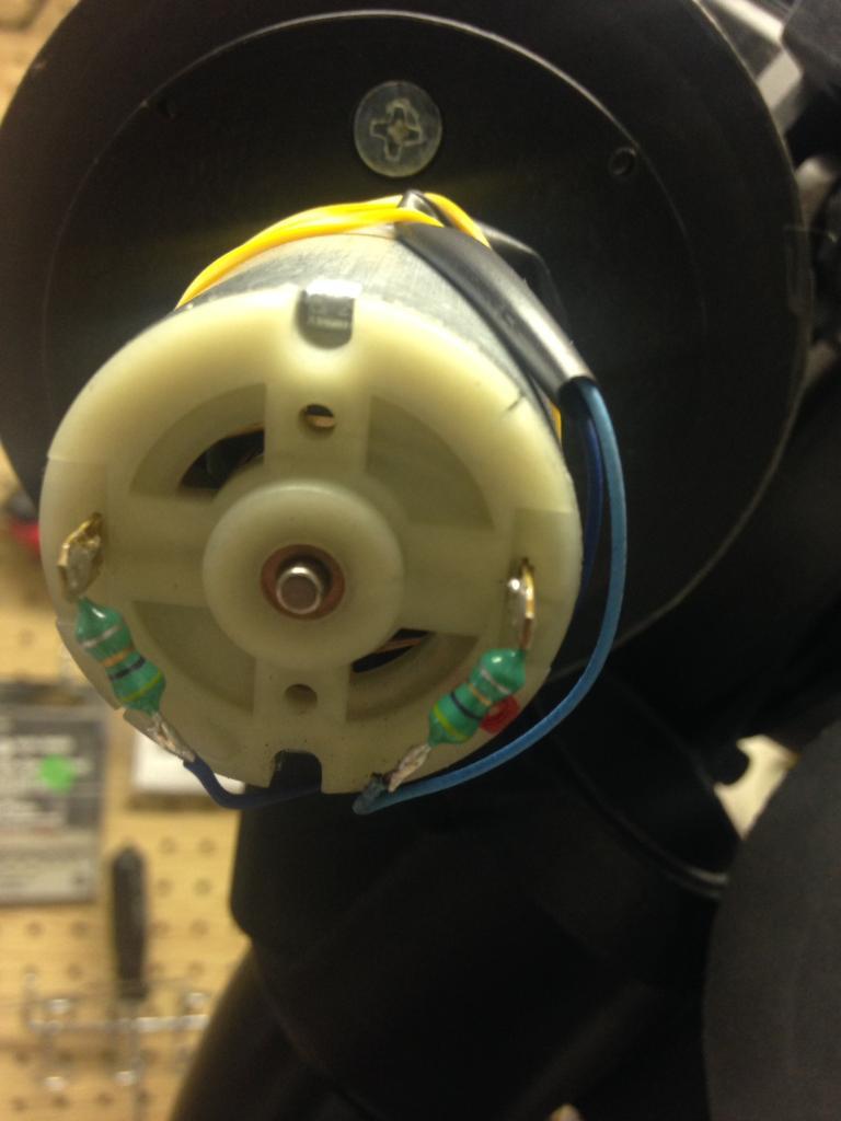
I am building a robot controller to replace an existing controller for the robot. The existing controller uses Mosfets and PWM to control 24 volt DC motors. I am doing the same with an Arduino and the Pololu DRV8801. The existing controller has a PWM frequency of 3.96khz (255 microseconds period).

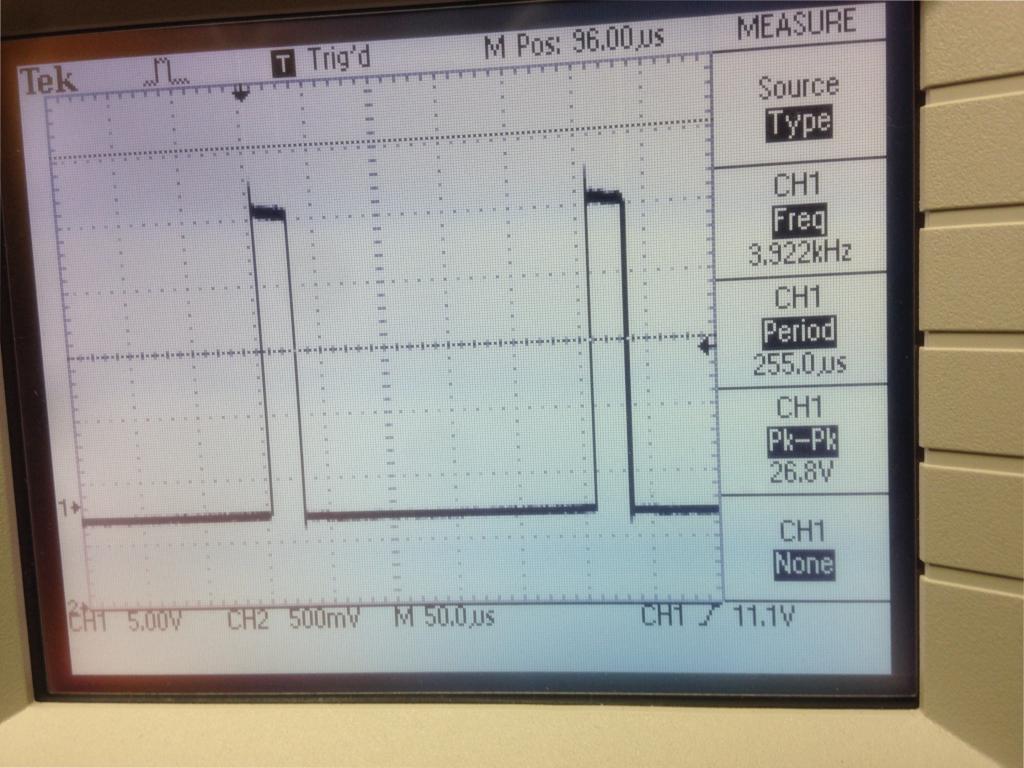
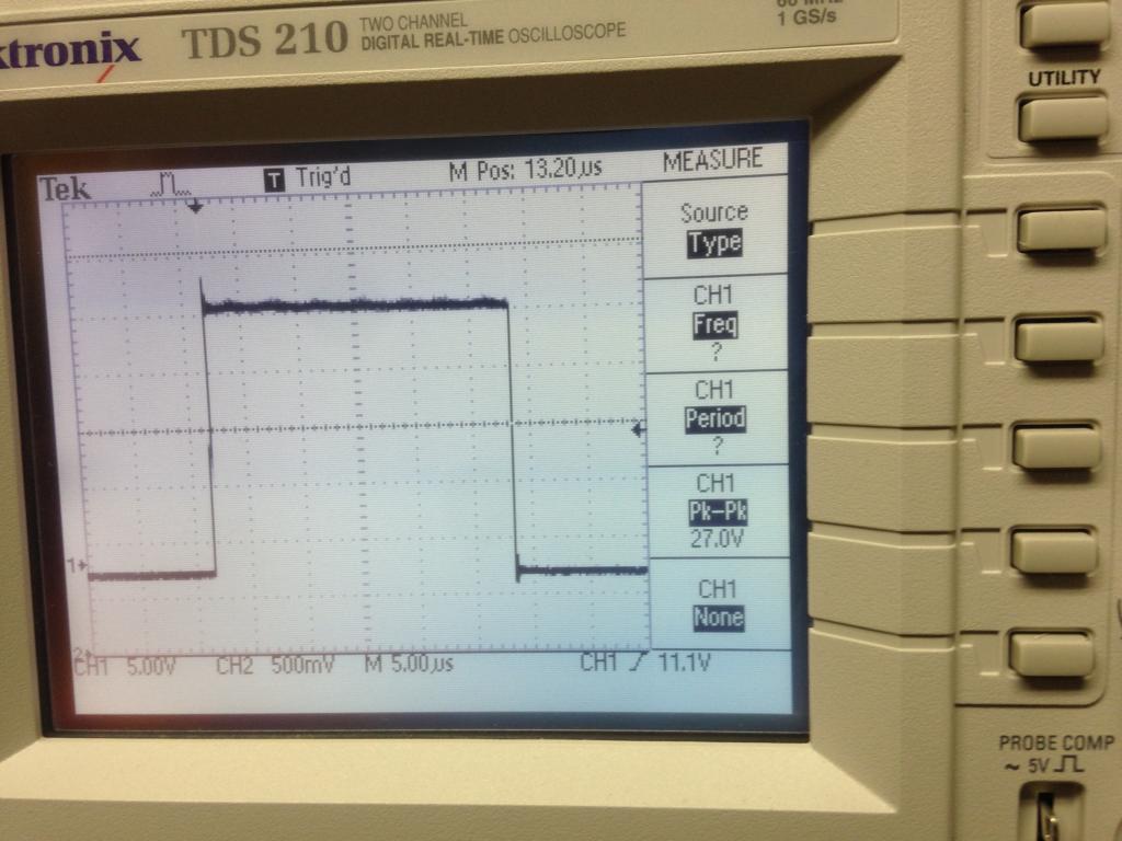
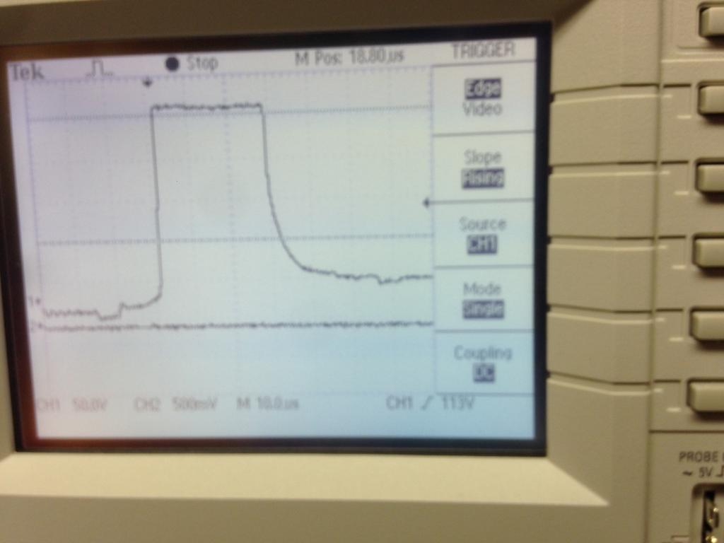
I am trying to send the same PWM frequency to the robot, but am finding that the motors won’t spin at the lower duty cycles. I need to be able to run the motors at low RPMs. If I look at the PWM waves on an oscilloscope, I see a nice square wave with the Mosfet controller. With the DRV8801, not so much. Here is the old controller’s wave:

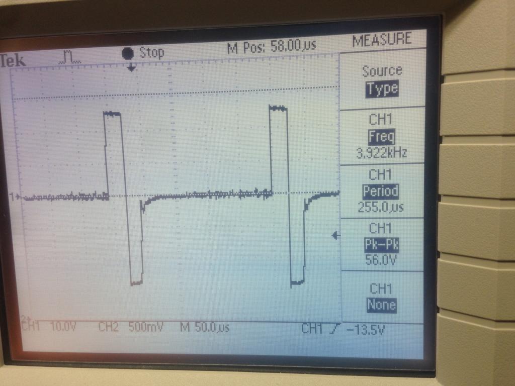
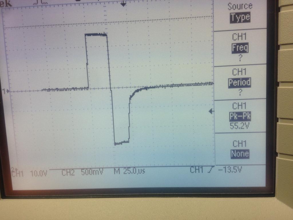
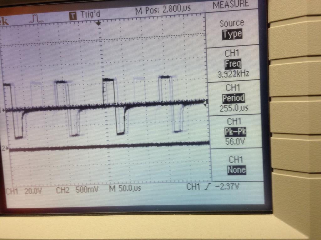
and here is the DRV8801 wave:

Both have the same PWM frequency and duty cycle, but you can see the MOSFET controller’s wave is much cleaner. That can move the motors at that duty cycle, the DRV8801 can’t.

Is there anything I can do to get this to work? Or does Pololu have another motor controller that would be better suited to my application?

  • Dave

Hello, Dave.

I am sorry you are having problems using your DRV8801 motor driver carrier. Without knowing more about your specific application, I cannot make a suggestion for a more suitable motor driver. Could you tell me more about your setup and application? What kind of motor are you using? Could you provide a link to its specifications or datasheet? How do you have things connected to the driver? Could you post pictures of your setup?

- Jeremy

It’s a 24 volt DC motor. I want to power it via PWM. It’s a fairly complex setup and board, can you be more specific about what information you need? I have the DRV8801 wired as per the instructions on your site.

The issue I’m seeing with the PWM wave is independent of the motor. That’s the wave I see even if the motor isn’t connected.

The PWM signal generated does not look bad to me. If thats the signal the motor receives, I would expect the motor to drive just fine. Does the signal change when the motor is connected?

What is the stall and free-run current of the motor? In my previous post, I asked if you could provide a link to its specifications or datasheet. Information about the motor’s stall and free-run current should be listed there. What are you using to generate the signals that you are sending to the driver? If you are using a microcontroller, could you tell us which one and post the code that is running on it?

- Jeremy

I’m running the code on an Arduino. I don’t know the specs on the motor. I didn’t build the original robot and don’t know the details on the motor. But again - if the motor isn’t connected, I still see the square waves as per the picture. And with the motor connected, with nothing else changed, the MOSFET controller can start the motor moving at a much lower PWM frequency than the 8801.

I’m sorry I don’t have all the information, but can you enlighten me as to what might be going on? Does it matter what the motor is? The issue to me seems to be that the PWM wave from the 8801 isn’t as “square”. As far as I can measure on an oscilloscope, everything else is the same - the power being fed to the controller, and the frequency and duty cycle of the PWM being fed to the motor. Is there anything else that could cause what I’m seeing, other than the fact that the 8801 has this “sloppy” wave?

[quote] The issue to me seems to be that the PWM wave from the 8801 isn’t as “square”.[/quote]Why do you think that matters? I don’t. If anything, the trace with the shoulder should deliver more net power to the motor.

It might be useful if you could post traces taken, with the motor attached, at low and high PWM on times.

Also helpful would be to measure the motor stall and free run current, which is very simple to do. Measure the stall current while applying a low voltage (say 3 V) with the shaft locked, then multiply by the appropriate factor.

BTW the DRV8801 is a MOSFET controller.

I thought that too Jim, about the “shoulder” but that’s the only difference I can see. The applied voltage is the same. The PWM frequency is the same. The duty cycle is the same. What else would explain the difference in the reaction of the motor?

I can definitely post more traces. Vut what do you mean by “high and low PWM on times”. I don’t know about measuring the stall current though. I don’t have anything to lock the motors with, it would involve dismantling hue machine more than I’m comfortable with, and if I damaged a motor, I don’t have a source for a replacement. But maybe if I do as you say and only give it 3 volts, I could lock it with my fingers. Still makes me a little nervous.

Another thing I don’t understand about how these motors are wired, and it shouldn’t be relevant to this PWM question since the wiring is the same for both controllers - but if you can explain this let me know. There are three resistors on each motor. One from each power line to the motor leads, and one connecting the motor leads. Something to do with back emf?

I doubt those are resistors on the motor leads. Capacitors are more likely, for noise reduction. Post a picture!

It is nearly impossible to troubleshoot a circuit if you don’t know the relevant parameters and for a motor, free run and stall currents are among the most important. Another way to estimate the stall current is to measure the winding resistance, while rotating the motor shaft very slowly to overcome brush contact resistance.

A brushed motor briefly draws the stall current upon startup. It could be that the DRV8801 is limiting the startup current, or current limiting in general. If that is the case, you could try a higher current driver like the VNH5019.

Ok, here is a picture.


This motor doesn’t have the resistor connecting the motor leads, but does have a resistor between the leads and the motors. The color codes are green, blue, gold, silver. If I look that up, it should be 4.6 ohms, but if I measure the resistance on my multimeter I get .5 ohms.

So could you elaborate on how to calculate the stall current by measuring the resistance? If I connect my multimeter to the motor leads (inside the resistors - I’m connecting right to the leads), I measure 7.5 ohms. If I turn the motor, the resistance goes up, and the faster I turn it the higher the number is, so it’s hard to know how fast to turn and which number to use. If it’s important, I could try your idea of applying a low voltage and stalling a motor, but that does make me nervous!

Thanks for your help!

- Dave

Those are inductors and they serve the same purpose as capacitors – noise reduction.

Taking the 7.5 ohm value for the winding resistance, the stall current at 24 V would be 3.2 amps. That is a bit too much for the DRV8801, and it could indeed be limiting.

Oh! Thanks for clearing that up.

And, I know the drv8801 can’t handle that current level, but the current draw never gets near that in this machine, not the entire machine, and not even close for a single motor. These motors get very little resistance in this machine. There are three of these motors, plus two stepper motors, plus another smaller motor. They all run at once, and the power supply is only a 2.5 amp power supply.

But back to my original question, if you could shed some light on why the drv8801 can’t get the motors moving at the same duty cycle and PWM frequency as the old controller, I’d appreciate it! And to be clear, the drv8801 CAN move the motors at that duty cycle at a lower PWM frequency (such as 490 Hz). It’s only at the higher frequencies that it works poorly.

It is difficult to tell what is going on without knowing what the signal to the motor looks like. Could you post an oscilloscope capture of your MOSFET controller’s output while it is driving the motor? Could you also post captures of the DRV8801 driver’s output when is driving the motor at a lower frequency and when it fails to drive the motor?

- Jeremy

Sure! I think you’re onto something.

Ok, here are two oscilloscope captures from the original controller, motor running, with a 27us duty cycle and a 3.9kHz (255us period) PWM frequency. (apologies for the upside-down images. They’re hosted on photobucket and look fine there, but when linked to here they’re showing up upside-down.)

The first shows the waveform and the second is zoomed in on a single wave:


And here is the same thing with the DRV8801:


So as you see - the waveform for the old controller looks basically the same whether the motor is running or not. But the wave with the motor running on my DRV8801 controller is very different! Can you explain what’s going on here?

Thanks!

- Dave

We tried duplicating your setup here but could not reproduce the problem. Could you tell me and post pictures of how you were measuring the motor outputs with the oscilloscope? Could you also post pictures of your overall setup, including how the driver is connected? If possible, could you try bypassing the inductors on the motor to connect it directly to the driver and see if that helps? One easy way to bypass the inductor is to clip test leads across them.

- Jeremy

Ok, thanks for your help!

Here is an image of the oscilloscope screen when I bypassed the inductors.

Basically the same signal, but it is noisier.

To get this oscilloscope reading, I connected the PWM outputs of the DRV8801 directly to test leads, connected the test leads to the motor connections, and clipped the oscilloscope leads to the test leads. I didn’t take a picture of that, it’s a lot of wires and didn’t seem useful. But I can send a pic if you want…

For the other readings, I connected the oscilloscope probes inline with the motor outputs of the DRV8801. The connections to the machine are via a DB25 cable, so I connect to a DB25 breakout box I have inline with the cable connecting the controller to the machine.

As far as my overall setup, it’s a custom PCB I built. There’s a bunch of stuff in there that’s irrelevant to what we’re talking about here, and it’s kind of proprietary, so I don’t want to post it on a public forum. But I can PM you the circuit diagram if you want.

As far as the DRV8801 connections go, I’m sending a PWM signal from an Arduino. The Arduino normally outputs a 490 Hz PWM signal, so I have some code to modify the system clock to send the 3.9kHz signal. I expect you know all about how to do that, but I can send you a link explaining it if you want, and it doesn’t seem relevant to what’s going on here. But maybe it is - what do I know.

My connections to the DRV8801 are as follows:

VCC → 5 volts
BRAKE-> GND
SLEEP-> Arduino digital pin
DIR-> VCC
PWM → Arduino digital pin (PWM output)
GND-> GND
FAULT → floating
CS-> Arduino analog input pin
VMM → 24 volts
OUT- → motor negative
OUT+ → motor positive
GND → GND

So pretty straightforward…

I’ve probably left some things out and you probably have more questions, so would it make sense if we talked on the phone instead?

Thanks again.

- Dave

And just to be clear - even though I know how to hook up an oscilloscope, I’m an electronics newbie. I don’t understand what we’re seeing with that wave. What does the part going down tell us? Why would we see that when the motors are connected, but if you disconnect the motors you get the normal square wave you’d expect. Does it have something to do with back EMF? And is this significant with regards to my main issue - that I can’t turn the motors at a lower duty cycle at a 3.9kHz PWM frequency?

Try setting the BRAKE pin high, as recommended. That should give better control at low PWM ratios.

Yes, I will do that in the next iteration of my board. But is that relevant to this issue? Having the brake pin low just means that the motor will coast when power is removed or decreased, making it slow down slower than you might want - correct? It wouldn’t prevent it from starting up at low duty cycles, would it? I can see how braking would keep it from starting up, but not that “not braking” would keep it from starting up…

[quote]I will do that in the next iteration of my board.[/quote]Do you want to solve this problem, or just argue about it?
Or, is it too difficult for you to cut a PCB trace?

I can’t cut the traces, the DRV8801s are mounted to female headers on the board, which obscure the traces to the pins. But I did manage to finagle setting BRAKE high, and that did seem to make a difference! So would you mind explaining what’s going on? Not being argumentative, just want to understand this. I don’t get why braking lets it run faster, nor do I understand the wave I was seeing.