
Hello. I am a bit new to this, an unable to understand why I am getting no output on AO1 and AO2.
I have Arduino pin ~10 sending PWM to PWMA. Pins ~5 and ~6 output LOW and HIGH to AIN2 and AIN1 respectively. Pin ~3 sends HIGH to STBY. All according to this tutorial: embeddedrelated.com/showarticle/498.php
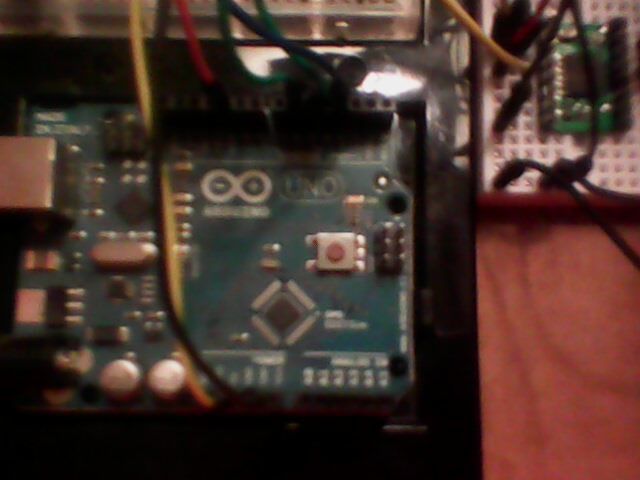
All of these outputs from the Arduino pins show correct output voltages using a multimeter: 0volts pin5, 5volts pin6, 5volts pin 3, varying voltage up and down pin10.
Power rail is tied to Arduino 5V out.
VCC and VMOT are tied to power rail.
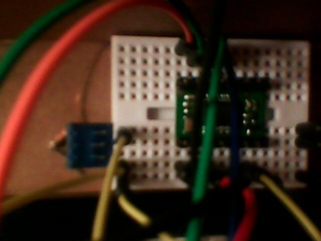
Ground rail is tied to Arduino GND.
Logic GND and motor GND are tied to ground rail.
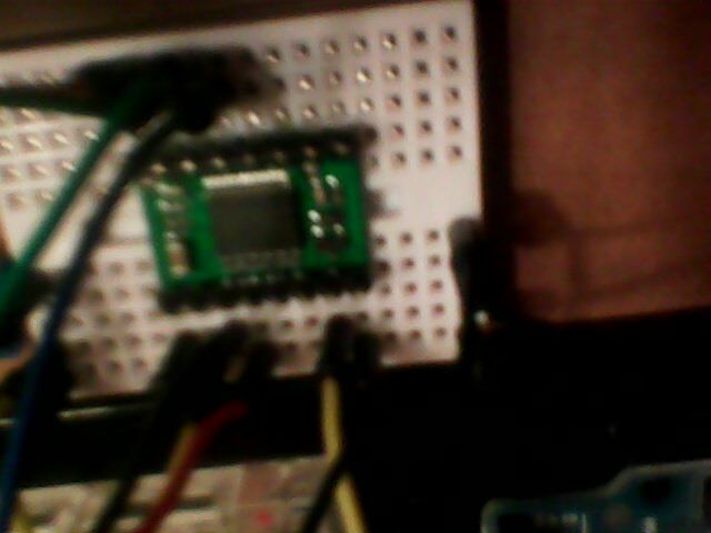
But I get no readings when I connect the multimeter to AO1 and AO2.
The code is the basic Arduino motor test code:
[code]/* ———————————————————–
-
| Arduino Experimentation Kit Example Code | -
| CIRC-03 .: Spin Motor Spin :. (Transistor and Motor) | -
———————————————————– - The Arduinos pins are great for driving LEDs however if you hook
- up something that requires more power you will quickly break them.
- To control bigger items we need the help of a transistor.
- Here we will use a transistor to control a small toy motor
- http://tinyurl.com/d4wht7
*/
int motorPin = 10; // define the pin the motor is connected to
// (if you use pin 9,10,11 or 3you can also control speed)
int ain2 = 5; // define the pin AIN2 is connected to, set LOW for clkwise
int ain1 = 6; // define the pin AIN1 is connected to, set HIGH for clkwise
int stndby = 3; // define the pin STBY is connected to, set HIGH for run
/*
- setup() – this function runs once when you turn your Arduino on
- We set the motors pin to be an output (turning the pin high (+5v) or low (ground) (-))
- rather than an input (checking whether a pin is high or low)
*/
void setup()
{
pinMode(motorPin, OUTPUT);
pinMode(ain2, OUTPUT);
pinMode(ain1, OUTPUT);
pinMode(stndby, OUTPUT);
// initialize serial communication with computer:
Serial.begin(9600);
}
/*
- loop() – this function will start after setup finishes and then repeat
- we call a function called motorOnThenOff()
*/
void loop() // run over and over again
{
digitalWrite(ain2, LOW); // turns the clkwise
digitalWrite(ain1, HIGH); // turns the motor clkwise
digitalWrite(stndby, HIGH); // turn on
motorOnThenOff();
motorOnThenOffWithSpeed();
motorAcceleration();
}
/*
- motorOnThenOff() – turns motor on then off
- (notice this code is identical to the code we used for
- the blinking LED)
*/
void motorOnThenOff(){
int onTime = 2500; //the number of milliseconds for the motor to turn on for
int offTime = 1000; //the number of milliseconds for the motor to turn off for
digitalWrite(motorPin, HIGH); // turns the motor On
delay(onTime); // waits for onTime milliseconds
digitalWrite(motorPin, LOW); // turns the motor Off
delay(offTime); // waits for offTime milliseconds
}
/*
- motorOnThenOffWithSpeed() – turns motor on then off but uses speed values as well
- (notice this code is identical to the code we used for
- the blinking LED)
*/
void motorOnThenOffWithSpeed(){
int onSpeed = 200; // a number between 0 (stopped) and 255 (full speed)
Serial.println(onSpeed);
int onTime = 2500; //the number of milliseconds for the motor to turn on for
int offSpeed = 50; // a number between 0 (stopped) and 255 (full speed)
Serial.println(offSpeed);
int offTime = 1000; //the number of milliseconds for the motor to turn off for
analogWrite(motorPin, onSpeed); // turns the motor On
Serial.println(onSpeed);
delay(onTime); // waits for onTime milliseconds
analogWrite(motorPin, offSpeed); // turns the motor Off
Serial.println(offSpeed);
delay(offTime); // waits for offTime milliseconds
}
/*
- motorAcceleration() – accelerates the motor to full speed then
- back down to zero
*/
void motorAcceleration(){
int delayTime = 50; //milliseconds between each speed step
//Accelerates the motor
for(int i = 0; i < 256; i++){ //goes through each speed from 0 to 255
analogWrite(motorPin, i); //sets the new speed
Serial.println(i);
delay(delayTime); // waits for delayTime milliseconds
}
//Decelerates the motor
for(int i = 255; i >= 0; i–){ //goes through each speed from 255 to 0
analogWrite(motorPin, i); //sets the new speed
Serial.println(i);
delay(delayTime); // waits for delayTime milliseconds
}
}
[/code]
Are my power inputs wrong? Should I be running (motor power) off a battery instead? Do I need a voltage regulator? Since I only really want a single PWM logic line per motor and I don’t need directional control, is there a simpler motor carrier? Would I be better off just cascading a couple of transistors into a Darlington pair? I really thought this would be simpler, but it is turning out to be more complicated than just using individual through-hole components.
I will be around to answer any further questions in 8 hours.