I’m currently using pololu jrk motor controller on several motors. I have set one as the master (USB Chained) and the others as slaved with UART fixed baud rate of 9600. Now I can control the boards fine by sending commands, but I’m still trying to figure out how to get the feedback from each of the boards.
My code for getting feedback is as follows, using C#. It works fine for getting the master feedback.
[code]public int ReadArmPosition(int DeviceNumber)
{
try
{
byte cmd4 = 0xA5;
byte[] bytesArray = new byte[1] { cmd4 };
            for (int i = 0; i < bytesArray.Length; i++)
            {
                serialPort.Write(bytesArray, i, 1);
            }

            byte[] result = new byte[2];
            serialPort.Read(result, 0, 2);
            int feedback = result[0] | (result[1] << 8);
            return feedback;
        }
        catch (Exception ex)
        {
            throw new Exception(ex.ToString());
        }
    }[/code]
Now if I try to get feedback from other devices, like the following, it still only receives feedback from the master no matter what device number I set.
Your serial command is incorrect. In the Pololu protocol (commands that start with 0xAA), the command byte needs to have its most significant bit cleared, so cmd4 should be set to 0x25. Also, the feedback variable reading command consist of three command bytes not four, so cmd3 is unnecessary. You can look at the “Variable Reading Commands” section in the Jrk USB Motor Controller User’s Guide for more information.
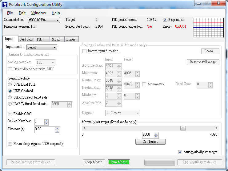
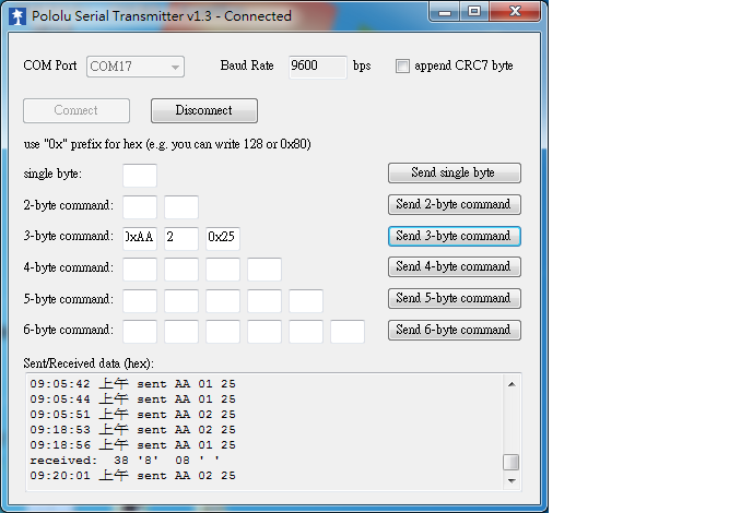
I did not see anything obviously wrong with your code. Can you post a screenshot of your Device Manager showing all the COM ports your Jrk devices are connected to and list the device number associated with each port, so I can verify that you are using the correct COM port and device number? Could you try sending the three-byte command 0xAA, DeviceNumber, 0x25 to your master Jrk device using the Pololu Serial Transmitter Utility and post a screenshot of the window here?
Also, please post your settings file for the master Jrk device. You can save the settings file by using the “Save settings file…” option under the “File” drop-down menu within the Jrk Configuration Utility.
Both screenshots of the Jrk Configuration Utility window show errors. From those error codes, it looks like you are getting the “Awaiting command” error. Is the red LED on for either Jrk controller?
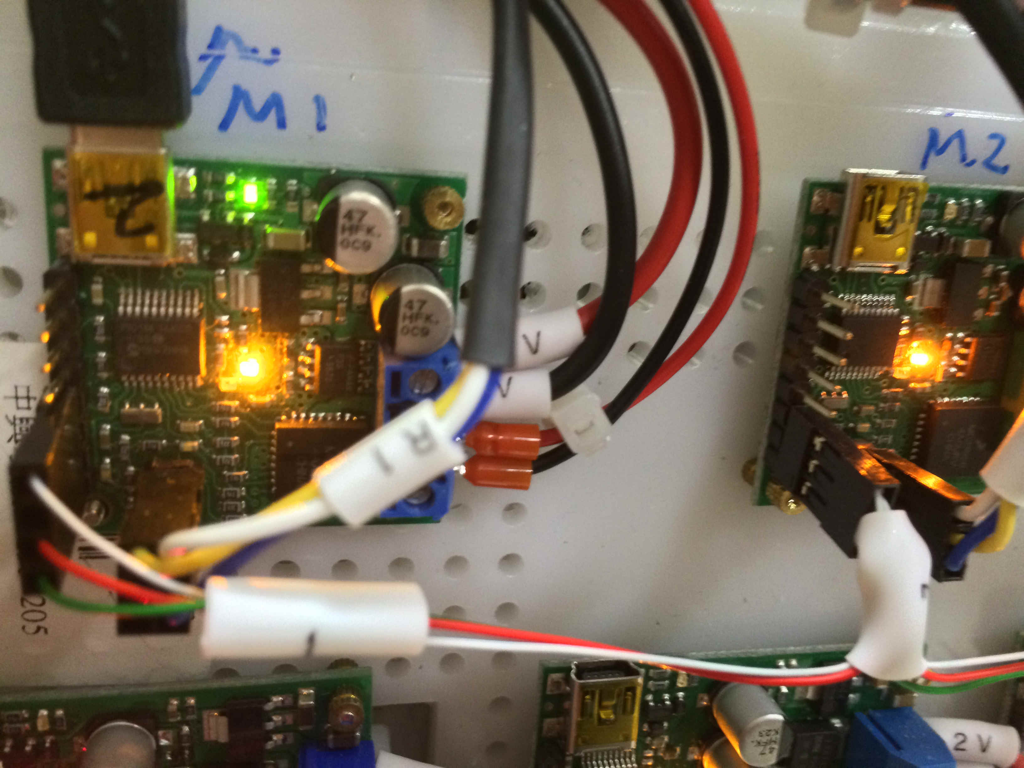
It is possible there is a connection issue between the master and slave device. Can you post pictures of your setup including all of your connections?
White thin line is TX from master to RX on slave. R1 labeled line is for feedback input,5v and GND. The others on the right side for board and motor power.
It looks like you are missing a connection from the RX pin of your master Jrk controller (indicated as M1 in your setup) to the TX pin on the slave device (marked M2), which is probably the reason why your master controller cannot read and return the slave’s feedback reading. There is a diagram in the “Daisy-Chaining” section of the Jrk user’s guide showing how to connect the master to many slave devices, which might be a useful reference for you. The AND gate in the diagram is optional if you are connecting a single slave device, however if you are planning to connect more than one slave in your system, you will need to use an AND gate to combine the slaves’ TX signals, which is also mentioned in that section.
By the way, it is not clear to me in the picture if there is a ground connection between your master and slave device. Please be sure everything in your system share a common ground and ensure each device is properly powered.
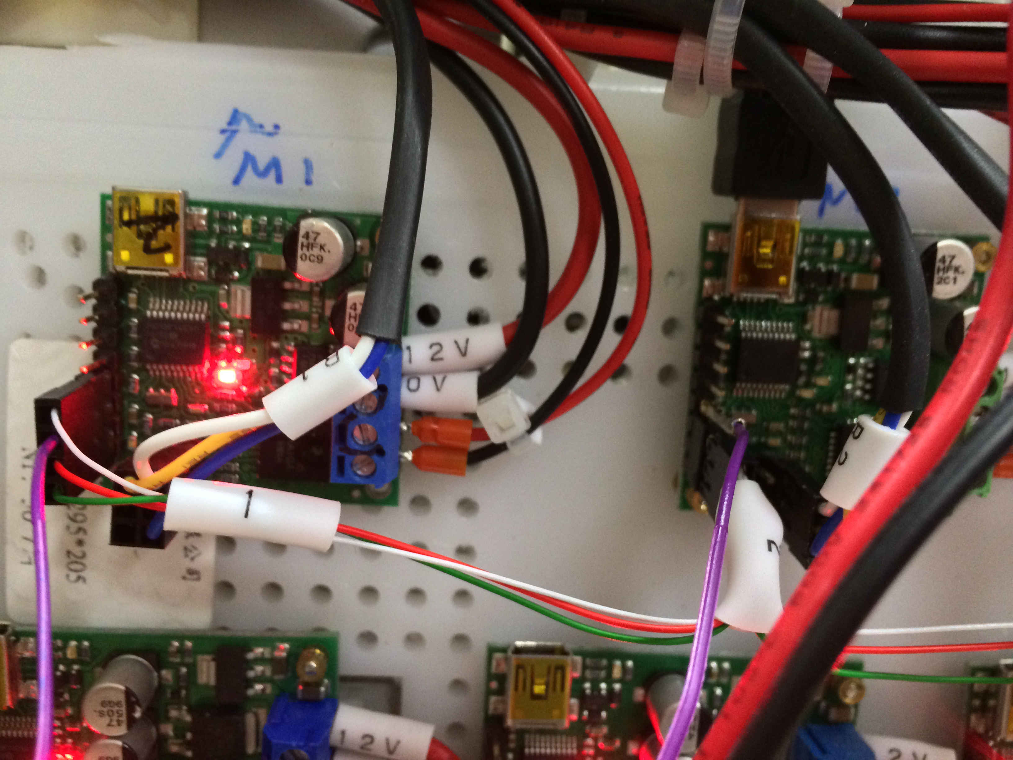
The purple line links from master RX to slave TX (there are more slaves, but I’ve only connected this one line for slave feedback for now, so no AND gate needed). Still not getting any feedback response from slave though. By the way, the board has red error light because the power was turned off when I was taking this photo.
I am sorry you are still having trouble getting feedback readings from your Jrk slave controller. I noticed in your recent picture the slave device (marked M2) is connected to USB instead of the master (marked M1). It is not clear to me what you are trying to do, can you clarify?
If you have access to an oscilloscope, can you verify there is a signal being transmitted on the slave’s RX pin from the master’s TX pin and post a screen capture of your oscilloscope’s measurements? The oscilloscope capture would allow us to see what is happening on the TX and RX lines and determine if the two devices are behaving as expected.

 no matter what device I’m trying to retrieve the feedback from.