I’m new to these so, I expect to make a few mistakes… Maybe someone can tell me where i screwed up.
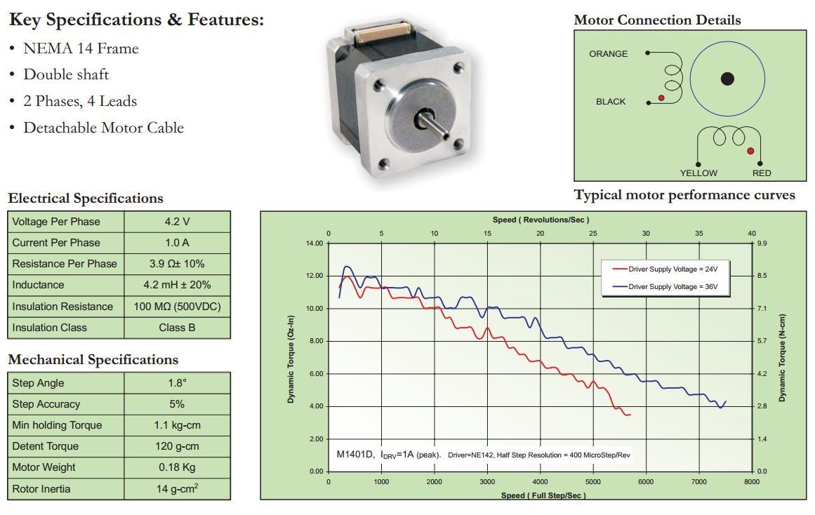
First, I’m using 4.5v 1A per phase BiPolar Stepper Motors.
The powersupply is a 2A 4.5-12v DC Powersupply. I have it set to 4.5v, and have tried kicking it up to 9v just to see what happens.
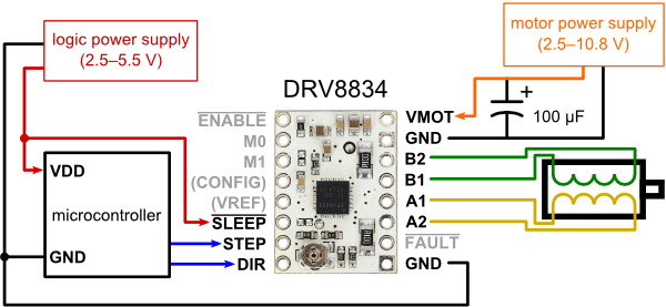
To test my motors, i have wired up per this schematic:
I have wired this up to an arduino mini, with 4.8 v power coming off of the microcontroller, and checked with the vendor to make sure that my wires are lined up right.
But for wiring Arduino to 8834:
Pin 8 → Direction
Pin 9 → Step
Sleep is attached to the microcontroller power.
At one point, I was able to get the motor to ‘hold tight’ by connecting the sleep to the 4.5v power of the motor, but it wouldn’t respond to step commands coming from the arduino.
So, i’m kind of at a stopping point. I’ve verified my connections and wires, and the motor isn’t even “snapping to” or holding tight when it gets power. Can anyone give me a better way of testing this for working? I’ll be dropping this in the place of an A4998 on a 3d Printer shield.
Thanks for replying back. I got some direction on the phone from support and made sure that the coil limit was set right. (now correctly set to .5)
So, I’m still running into the same problem I originally had. The motor is in a ‘lock’ mode. Has power, but not responding to commands to step. Because these are not popular motor types, I asked the seller on ebay to give me the codes again, and the data sheets. I am questioning now if the wiring he gave me is even right.
This is the wiring he gave me:
B1 – Yellow
B2 – Red
A1 – Black
A2 – Orange
I’m going to assume from the below picture, that the wires end with the red dot indicate they should be similar some how. I’m not sure what that signifies, so i’m coming here for guidance.
At this point, intuition makes me lean towards incorrect wiring. But I also want to make sure that i’m using the correct driver for this motor. Thanks!
Here is a quick example of the code i’m using to test with:
int Distance = 0;  // Record the number of steps we've taken

void setup() {
  pinMode(8, OUTPUT);
  pinMode(9, OUTPUT);
  digitalWrite(8, LOW);
  digitalWrite(9, LOW);
}

void loop() {
  digitalWrite(9, HIGH);
  delayMicroseconds(1000);
  digitalWrite(9, LOW);
  delayMicroseconds(1000);
  Distance = Distance + 1;   // record this step

  // Check to see if we are at the end of our move
  if (Distance == 3600)
  {
    // We are! Reverse direction (invert DIR signal)
    if (digitalRead(8) == LOW)
    {
      digitalWrite(8, HIGH);
    }
    else
    {
      digitalWrite(8, LOW);
    }
    // Reset our distance back to zero since we're
    // starting a new move
    Distance = 0;
    // Now pause for half a second
    delay(5000);
  }
}
Have you checked the voltages on the motor driver and the MCU with a multimeter? You may not have power and ground connected properly. The “power rails” along the edges are probably not connected across the board, which you appear to have assumed. Also, on some breadboards, they are split in the middle lengthwise and require jumpers.
In the example program, reversing the direction and resetting the distance to zero when the move is done doesn’t really accomplish anything. The shaft shouldn’t turn, but perhaps that is what you intended.
Finally, you can check the coil connections with the resistance function of the multimeter. It does not matter which set of coils is connected to the motor driver A and B outputs, or which orientation. At most the direction of forward motion is changed.
Jim, thanks again for taking the time to help me out.
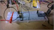
If I were to measure the voltage across the A1/A2, and my supply voltage is 4.5 v, what should I see across those 2? I’ll post a cleaned up picture of my setup tonight when I get home.