I am pretty darn clueless when it comes to electronics and code so, I’m hoping for a bit of guidance with this project. I am moving away from the DC motor I’ve been using on my portable star (barndoor) tracker because of the pains of constant adjustments to achieve the needed (accurate) 1 rpm. Anyway, in a perfect world, I would like to have the stepper motor I ordered run at a constant, smooth 1 RPM in one direction. That’s all it has to do, just on or off.
I am now searching for the correct wiring and code needed to get me going. I have found the basic wiring diagrams but I’m unclear as to set up for micro stepping if that will assist with smoothness.
If anyone has ever run a stepper this slow or can otherwise assist with any insight, it will be greatly appreciated. I have much to learn, this is a new world for me
(fwiw I’m a mechanical tech by trade (25+ yrs) and soldering is not a problem for me)
Components on order:
Arduino Uno R3
Pololu item #: 1200 Stepper Motor
Pololu A4988 stepper motor driver carrier with voltage regulators
330 uF capacitor
Are you sure your stepper motor is strong enough? A stepper motor will be easier to code the speed though, because it either runs at the speed you tell it to, or stalls.
The “acellstepper” library will be your friend. It works at low speed very well. The first revisions of the library did not, but I believe they’ve fixed it. You can look up “acellstepper telescope driver” for some people doing crazy slow movements with that library:P
Microstepping will be smoother. But my guess is you want a gearbox between the stepper motor and whatever you’re turning, and that will smooth out the motion better and get you more torque as I’d expect you’d need for anything large.
Although slightly wary to, I’d like to suggest there are ways you can get the DC motor to run at a constant speed. Were you using a pololu motor? If there is the same motor available with an “encoder” on the back, it can be used to create some closed-loop control on the speed.
Alternatively, you can get moderate speed control using a driver with current feedback, which combined with knowledge of a few elements of your system can give you partial closed loop feedback.
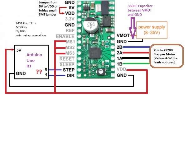
Microstepping can help you achieve smoother motion with stepper motors. I do not see any reason you should not be able to achieve 1RPM without too much trouble. The “Minimal wiring diagram for wiring a 5V microcontroller to an A4983/A4988 stepper motor driver carrier with voltage regulators (full-step mode)” on the A4988 product page shows how you can wire the A4988 to your Arduino. The chart under the “Step (and microstep) size” heading on the same product page shows the settings needed for each micro-stepping mode. You can connect the “LOW” pins to GND and the “HIGH” pins to VDD.
I think there’s something about the torque being somewhat less, but sadly I’ve never really gotten to the bottom of torque and microstepping. But to microstep the motor has to modulate between two full steps, using a partial current of the discrete step before and after the microstep. So that conceptually makes a decent reason why the torque can be less than full-stepping. But I don’t know why you couldn’t just increase the current limit, since you would know that the microstepping requires partial-currents.
So to get to the bottom of that I’d google “microstepping reduced torque” or something like that.
The only other tradeoff I can think of is that if your microcontroller has a hard time sending the step commands. For example if it has a speed limit of 4000 step commands/s on regular steps, then it is limited to 4000/16=250 full steps on 1/16th mode. But that’s obviously not an issue in your case.
And it’s mostly just an issue with bulky code, since most microcontrollers are plenty fast enough to toggle a pin quickly.
Ok, having compiled what I currently believe I need from a number of sources can you guys give it a once over and see if it is correct before I begin soldering?
My biggest uncertainty is the Step and Direction connections on the Arduino - are these correct?
I will need some male pins to interface with the arduino, can anyone recommend the best type? If 90 degree versions exist that would likely be best for my application,
I just don’t know what they are referred to as.
oh yea, what gauge wire should I use?
Sorry again for all the newb Qs , I’m more accustomed to grease and metal chips
[quote=“photon_trap”]Ok, having compiled what I currently believe I need from a number of sources can you guys give it a once over and see if it is correct before I begin soldering?
My biggest uncertainty is the Step and Direction connections on the Arduino - are these correct?
I will need some male pins to interface with the arduino, can anyone recommend the best type? If 90 degree versions exist that would likely be best for my application,
I just don’t know what they are referred to as.
oh yea, what gauge wire should I use?
Sorry again for all the newb Qs , I’m more accustomed to grease and metal chips[/quote]
Sorry for the late responses. I dont go on the forums much. I think Derril mostly answered your questions, I have a few additions
(1) i dont notice anything wrong with the dir/step connections. looks fine
(2) Yes! 90 degree angle versions exist; I don’t know if Pololu sells them. I’ve usually seem them as <<0.1" right angle header"
(3) The gauge wire is not super important. The current you can expect going into the driver is less than your current limit going to the stepper motor, usually by a good bit. IF you have a 12V power supply and 4V motors, and the driver board is set to 2A, then you have 4A total going to the stepper motors (there are two phases.) That’s 4V*4A = 12V *I-in => In=1.33A, much less. So you want wire that can easily carry 1.33A, and most basic wires ~26-22 gauge would be fine, I think. For the signal wires basically anything within reason works, but I wouldn’t go under 28-30 gauge. It’s just easy to snap and all.
Hey thanks for your input guys, I appreciate it a lot! Hopefully, I’ll get it soldered up this weekend then it’s on to the code -
I found this (below)- is this what I should use for just simple constant speed?
Would I adjust the speed values near the bottom for time between steps in milliseconds?
For my needed 1 RPM: 1 min = 60,000 milliseconds, i have 3200 “steps” (@ 1/16th step) so, 18.75 would be correct?
Or, am I all mixed up?
// AFMotor_ConstantSpeed.pde
// -*- mode: C++ -*-
//
// Shows how to run AccelStepper in the simplest,
// fixed speed mode with no accelerations
// Requires the AFMotor library (https://github.com/adafruit/Adafruit-Motor-Shield-library)
#include <AccelStepper.h>
#include <AFMotor.h>
AF_Stepper motor1(200, 1);
// you can change these to DOUBLE or INTERLEAVE or MICROSTEP!
void forwardstep() {
motor1.onestep(FORWARD, SINGLE);
}
void backwardstep() {
motor1.onestep(BACKWARD, SINGLE);
}
AccelStepper stepper(forwardstep, backwardstep); // use functions to step
void setup()
{
Serial.begin(9600); // set up Serial library at 9600 bps
Serial.println("Stepper test!");
stepper.setMaxSpeed(50);
stepper.setSpeed(50);
}
void loop()
{
stepper.runSpeed();
}
Thanks,
I don’t think I understand what Library means - do I just adjust then upload these lines of code as is, or do in need to upload some other code as well?
Soldering is still on my to-do list so I have not yet attempted loading code
A library is a collection of code. For now, you do not have to modify the code or adjust your hardware configurations; just make sure that the libraries you referenced in your code are installed prior to uploading the sketch to your Arduino Uno. To reference a library, you would need to add a #include line followed by the filename of the library encapsulated in <> at the top of the sketch file you want to use the library’s functions from. For example, #include <AFMotor.h>. You might find it useful to read this article on Adafruit’s site, which explains in detail how to use and install Arduino libraries.
So the “speed” parameter of accellstepper acels a “step/second” command.
You want to take 3200 to make a full revolution. That’s 16 microsteps/step * 200 steps/revolution . So if you want that revolution in 60 seconds, 3200/60 = 53.3333 steps/second.
Then for acceleration, I still recommend an acceleration profile. You can later try if you don’t need it by progressively increasing the value till it basically doesn’t exist. You’ll maybe want something like 50. So for the first second it’ll take roughly 2 seconds to take 50 steps [don’t quote me on this, I forget how linear the acellstepper profile is.]
So maybe a good value is “54/steps” for the speed and “54” for the acelleration. Or just “53steps/second” and “100” for the acelleration. I really don’t know. depends how precise you want this all, basically.
Hopefully the restof the tutorials help with the code.
I am not very familiar with the Easy Driver, but it looks like it uses the same step and direction type interface as the A4988, so code written for the Easy Driver might work for the A4988.
The only difference between two “step/dir” type stepper drivers is that you might need to initiate different pins for the code, because you happen to be connecting to the step/dir pins with different pins on your microcontroller.
You might notice on the web more exotic stepper drivers that receive “serial command” or other types of directional commands, but mostly the convention is for drivers to have a “step/dir” pin. At high speeds sometimes one driveror another has minute differences, but usually code for 1 still works on the other.
OK… I have been reading for 9 months now - just kidding, life and other projects got in the way for a while and, rather than start a new thread, I decided to resurrect this one in case others need the same help as me.
Good news, I got it all soldered up and, using the very simple sketch below, it runs at what is very close to the desired 1 RPM !!! (Whoo Hoo!!) But, something seems off as the motor generates more heat than I expected. It is very warm to the touch, >106 F by my 20 dollar IR thermometer. the 8 AA alkaline batteries I have as temp power are warm too as one would expect.
Is this a consequence of running such a simple sketch or something that is to be expected? Sure seems to be drawing a LOT of current… Any suggestions are appreciated!
edit: I just realized i did not set the current limit on the a4988. Could that be cause of the heating the problem? (there is no load on the motor)
And also, after running it for 5 min, the speed, which seemed mathematically appropriate (?) is off, and after 5 revolutions, I am off by about 15 or so degrees. My goal is to maintain, as precisely as I can, just one speed on power on, either 1.00 or 2.00 RPM. That’s it, just run at constant speed and stop on power off. (final speed TBD, dependent on gearing used)
Thanks!
Ref: Arduino Uno
a4988 stepper driver w/VR #1200 stepper Motor
wired as noted in previous schematic
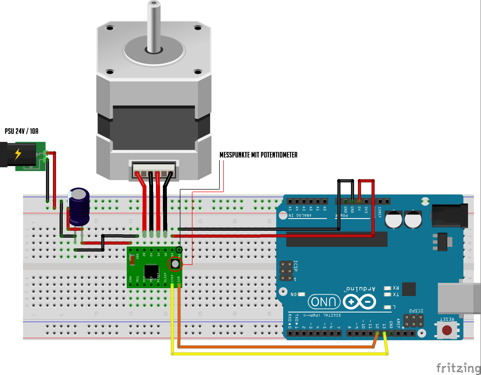
You should always set the current limit for your stepper motor.
In case of the A4988 driver, you can have a look at the image attached (please ignore the PSU specifications). Here you can find the measuring points with your volt meter. You attach - to the GND pin and + to the potentiometer. At the product page you can find the equation to set the current limit for your driver:
Current Limit = VREF × 2.5
So for the desired 1,2A current draw of the motor, you should set your VREF to 0,48V.
I am curious about whether the motion of the stepper motor is really perfectly smooth? Because even though you use micro stepping this isn’t a perfectly smooth motion, it may suite your needs in your specific project, but it’s not a perfect smooth motion, is it? I don’t understand why a DC motor is hard to run at constant speeds?