Thanks,
I don’t think I understand what Library means - do I just adjust then upload these lines of code as is, or do in need to upload some other code as well?
Soldering is still on my to-do list so I have not yet attempted loading code
Thx
Thanks,
I don’t think I understand what Library means - do I just adjust then upload these lines of code as is, or do in need to upload some other code as well?
Soldering is still on my to-do list so I have not yet attempted loading code
Thx
Hello.
A library is a collection of code. For now, you do not have to modify the code or adjust your hardware configurations; just make sure that the libraries you referenced in your code are installed prior to uploading the sketch to your Arduino Uno. To reference a library, you would need to add a #include line followed by the filename of the library encapsulated in <> at the top of the sketch file you want to use the library’s functions from. For example, #include <AFMotor.h>. You might find it useful to read this article on Adafruit’s site, which explains in detail how to use and install Arduino libraries.
- Amanda
Some good background:
schmalzhaus.com/EasyDriver/E … mples.html
and
sparkfun.com/tutorials/400
So the “speed” parameter of accellstepper acels a “step/second” command.
You want to take 3200 to make a full revolution. That’s 16 microsteps/step * 200 steps/revolution . So if you want that revolution in 60 seconds, 3200/60 = 53.3333 steps/second.
Then for acceleration, I still recommend an acceleration profile. You can later try if you don’t need it by progressively increasing the value till it basically doesn’t exist. You’ll maybe want something like 50. So for the first second it’ll take roughly 2 seconds to take 50 steps [don’t quote me on this, I forget how linear the acellstepper profile is.]
So maybe a good value is “54/steps” for the speed and “54” for the acelleration. Or just “53steps/second” and “100” for the acelleration. I really don’t know. depends how precise you want this all, basically.
Hopefully the restof the tutorials help with the code.
Thanks very much for the links and Info, I’ll get ta readin’ !
Is code specific to the driver used? For example, would code written for Easy Driver be expected to work with my A4988?
Thanks
Hello.
I am not very familiar with the Easy Driver, but it looks like it uses the same step and direction type interface as the A4988, so code written for the Easy Driver might work for the A4988.
- Amanda
The only difference between two “step/dir” type stepper drivers is that you might need to initiate different pins for the code, because you happen to be connecting to the step/dir pins with different pins on your microcontroller.
You might notice on the web more exotic stepper drivers that receive “serial command” or other types of directional commands, but mostly the convention is for drivers to have a “step/dir” pin. At high speeds sometimes one driveror another has minute differences, but usually code for 1 still works on the other.
OK… I have been reading for 9 months now - just kidding, life and other projects got in the way for a while and, rather than start a new thread, I decided to resurrect this one in case others need the same help as me.
Good news, I got it all soldered up and, using the very simple sketch below, it runs at what is very close to the desired 1 RPM !!! (Whoo Hoo!!) But, something seems off as the motor generates more heat than I expected. It is very warm to the touch, >106 F by my 20 dollar IR thermometer. the 8 AA alkaline batteries I have as temp power are warm too as one would expect.
Is this a consequence of running such a simple sketch or something that is to be expected? Sure seems to be drawing a LOT of current… Any suggestions are appreciated!
edit: I just realized i did not set the current limit on the a4988. Could that be cause of the heating the problem? (there is no load on the motor)
And also, after running it for 5 min, the speed, which seemed mathematically appropriate (?) is off, and after 5 revolutions, I am off by about 15 or so degrees. My goal is to maintain, as precisely as I can, just one speed on power on, either 1.00 or 2.00 RPM. That’s it, just run at constant speed and stop on power off. (final speed TBD, dependent on gearing used)
Thanks!
Ref: Arduino Uno
a4988 stepper driver w/VR
#1200 stepper Motor
wired as noted in previous schematic
void setup() {

  pinMode(4, OUTPUT);

  pinMode(5, OUTPUT);

  digitalWrite(4, LOW);

  digitalWrite(5, LOW);

}


void loop() {

  digitalWrite(5, HIGH);

  delay(18.75);

  digitalWrite(5, LOW);

  delay(1);

}You should always set the current limit for your stepper motor.
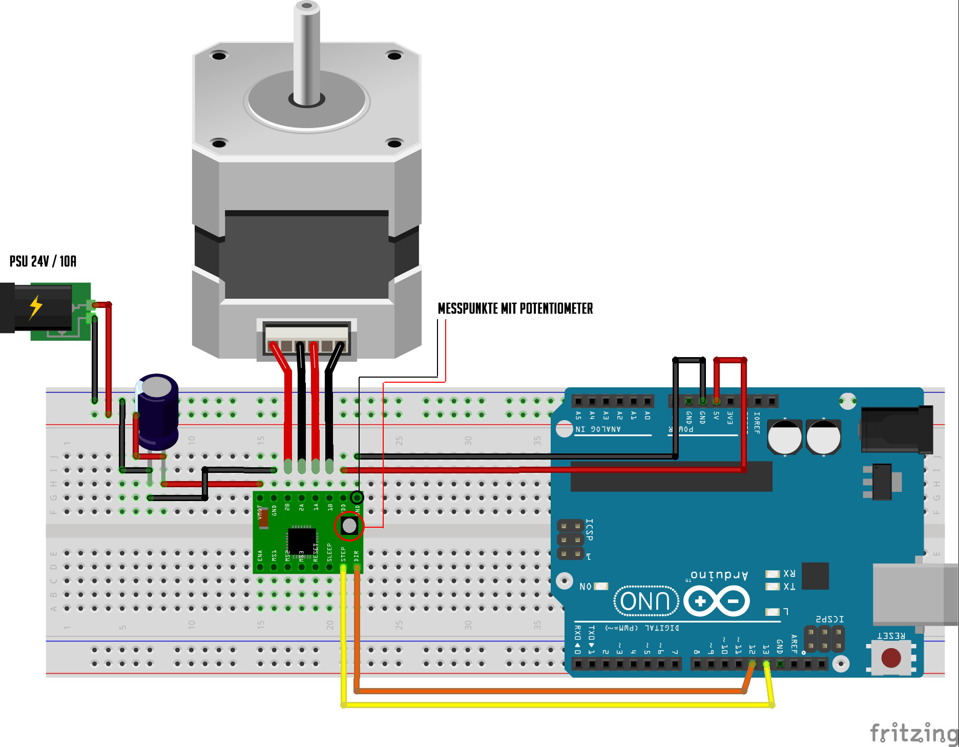
In case of the A4988 driver, you can have a look at the image attached (please ignore the PSU specifications). Here you can find the measuring points with your volt meter. You attach - to the GND pin and + to the potentiometer. At the product page you can find the equation to set the current limit for your driver:
Current Limit = VREF × 2.5
So for the desired 1,2A current draw of the motor, you should set your VREF to 0,48V.
I am curious about whether the motion of the stepper motor is really perfectly smooth? Because even though you use micro stepping this isn’t a perfectly smooth motion, it may suite your needs in your specific project, but it’s not a perfect smooth motion, is it? I don’t understand why a DC motor is hard to run at constant speeds?
Thanks for the info on setting the current limit. As for the smoothness, yes, you are correct, it is not perfect, even at 1/16 microsteps, but it is well within acceptable limits since the gears
(or in my case belt) will easily absorb any irregularities that matter (I actually doubt there are any as most of this shooting is done with very short focal lengths).
As for the DC motor, it requires time consuming verification and adjustment to maintain a constant, precise (a major requirement)
speed, dependent on battery voltage. It is by all means workable, but I am seeking simplification as I usually am shooting time-lapse and stationary stills at the same time.
I set the current limit (.48 volts X 2.5 = 1.2A) and the heating problem is solved. (!)
My next question is regarding stepping mode. (please bare with me, this is all new to me…)
Having set up the a4988 for 1/16th microstep resolution, (MS1,2 and 3 all powered as per schematic below) I was expecting to feel a fine “vibration” (3200 per motor revolution) on the motor shaft when running.
What I am actually feeling (and seeing) is more like full step mode of 200 per rev.
Is this normal or am I, for some reason still in full step mode?
Thx
Update: using the sketch below I have the setup running at VERY close to 2 RPM and I am happy with that for sure.
I am however, curious about the values. I was under the impression that this was all mathematically calculable, but the values I ended up with make no sense to me, specifically, the line: stepper.setSpeed (426.45);
426.45 is … delay in microseconds between steps? Steps per second? What the heck? This is not making any sense to me, and I suspect there is a high likelihood that something is amiss in my sketch so I’m sure someone can explain.
I am a bit uneasy not knowing the explanation for this BUT, I gotta say this is fun in some kinda strange way- ha! (I’m a mechanical tech, not a sparky or coder person)
The following got me to as perfect a 2 RPM as my cell phone timer app, a printed degree wheel and 16 minuets could muster, but IDK exactly why…
#include <AccelStepper.h>
#include <MultiStepper.h>

// ConstantSpeed.pde
// -*- mode: C++ -*-
//
// Shows how to run AccelStepper in the simplest,
// fixed speed mode with no accelerations
/// \author  Mike McCauley (mikem@airspayce.com)
// Copyright (C) 2009 Mike McCauley
// $Id: ConstantSpeed.pde,v 1.1 2011/01/05 01:51:01 mikem Exp mikem $
#include <AccelStepper.h>
AccelStepper stepper; // Defaults to AccelStepper::DRIVER (2 pins) on 5, 4
void setup()
{
   stepper.setMaxSpeed(1000);
   stepper.setSpeed(426.45);
}
void loop()
{
   stepper.runSpeed();
}Hello.
Unfortunately for your battery life, that sort of temperature is normal for a stepper motor like that. Stepper motors generally draw full power when they are not moving in order to maintain their holding torque. Setting the current limit lower might help, but the motors will still probably be warm.
I am not familiar with the AccelStepper library. Different stepper motors can have different numbers of steps per revolution, and microstepping also changes the number of times the step pin is toggled per full revolution. I do not see anything that looks like it sets that up in the example code you posted that uses the AccelStepper library.
In both the programs you posted, it looks like you are using decimal numbers as arguments in some function calls that might not take decimal number arguments (stepper.setSpeed(426.45); and delay(18.75); for instance). It is possible that these numbers are being rounded or truncated.
It sounds like you had pretty good results with your original code. If you need more precision in your delay, you could use the delayMicroseconds(i); function. As you noted, you would want one step signal every 18.75ms (or 18,750 us) but you should keep in mind that the 1ms delay after you toggle pin 5 low in your code counts in the total for the loop.
Missed steps can occur if there is too much resistance in the mechanical load driven by the stepper motor or if the current limit is too low. In microstepping mode, these missed fractions of a full step can build up, which could make the motor feel like it’s taking larger steps.
-Nathan
Thanks for your reply Nathan!
With regard to the delayMicroseconds(i) function you referred to, I incorporated it into my original sketch and have it running, I have a question regarding the balance of delay between the first (HIGH to LOW) and second (LOW to HIGH). Should the total delay required (in my case somewhere near 9375 for 2RPM - 6400 steps) be split between the two delays or… ?
I have run the first delay at fifty and also at one with the second delay at 9375 and both run with slightly differing results, but I was wondering if there is a preference for some other reason I am not (yet) aware of.
The only means of checking is a stopwatch app and progressively longer test times to exaggerate error - The 9375 value will need some tweaking for whatever reason I think
Thanks again, I appreciate your help!
void setup() {

      pinMode(4, OUTPUT);     // Dierction Pin

      pinMode(5, OUTPUT);     // Step Pin

      digitalWrite(4, LOW);

      digitalWrite(5, LOW);

    }


    void loop()
{
  digitalWrite(5, HIGH);   // sets the pin on

  delayMicroseconds(1);        // pauses for _  microseconds

  digitalWrite(5, LOW);    // sets the pin off

  delayMicroseconds(9375);        // pauses for _ microseconds between steps,  close to 2.0 RPM
}Hello.
There is a limit to the speed at which the stepper driver can respond to a signal and for the A4988, that limit is 1us. There is no real reason to be close to the limit, so you might want to change the timing of your delays to something like 5us/9370us. Other than that, I cannot think of a reason why the split between HIGH time and LOW time would affect the step rate.
I think it will be difficult to improve accuracy without making the code more complex. You should keep in mind that the operating frequency of the chip’s clock is about 1/16th of a microsecond and functions can hide code that can take many clock cycles to execute. For instance, the digitalWrite() functions might take several microseconds to execute. There are ways to further improve this, but these sorts of errors are similar in magnitude (one part in 10,000) to the sort of errors caused by variations in the frequencies produced by the clock crystals used for timing by the board itself. I would expect these sorts of timing variations to also be present in devices like stop watches or even camera timers.
If you are noticing errors smaller than 1 part in 1,000, you could look at the BlinkWithoutDelay example included with the Arduino IDE for a code structure that will have slightly better accuracy (your code is very similar to the basic Blink example). There is a micros() function that is similar to the millis() function. If you are noticing errors larger than that, you could be having problems with missed steps, so you could look at ways to decrease the mechanical load on the stepper or increase the current limit for your stepper motor if you are under the limit.
As a final note, I modified your post to use code tags around the code. If you use those in the future, it makes it easier for everyone to follow your posts. You can use them by writing the first part of the following tag before your code and the second part after it:
[code]your code here[/code]-Nathan
Thanks for your suggestions and help Nathan and everyone. It is appreciated very much.
I will adjust the delays per your suggestion, make some final tweaks ( to achieve accuracy far in excess of that which is required - ha) and call this part of the project complete!
Heyo! Haven’t checked in for ages, but wanted to give feedback about the “cogging” effect you sort of saw. I believe from what you described, the stepper current limit might be too high to effectively deliver the microstepping waveform you wanted.
What you could try is, if your power requirements allow it, reduce your current limit very slowly until you hear the discrete steps go away.
This is a common problem with extruder motors on 3D printing, that is why I think you might be having this experience (based on your descriptions.)
There may be other things going on and if it’s somethingy you wanted to explore more carefully please remind me again:
Your motor voltage rating, and current rating
Your driving voltage (PSU voltage)
Your expected current limit (I think you said it was 1.2A)
I am not sure I really know what it would be besides too high of a current limit, but maybe we can both notice something if we look at it. That said, it might also not be a big concern for you.
Thanks Tomek!
I will give that a shot. I was not sure the current limit could be safely adjusted with the motor running.
I have switched to a smaller (and lighter) motor so, I need to re-adjust the current limit anyway - but with the smaller motor I’m not sure what I will be able to get away with…
Ah! Ok, sounds like you’re still working on things. Great to hear that there’s incremental effort tweaking things.
May I ask what the reason is for changing to a smaller motor?
Weight. The whole mount, with a camera and lens (both pretty heavy) puts one heck of a moment on the tripod and head so, I attempt to minimize this as best I can dimensionally and physically.
I will post a pic of the setup when I finish the new motor installation.
Picture will help, cool. Yeah, sometimes you can also get away with moving the motor off-assembly, via clever use of lines and belt. Or you might just find a smaller motor plenty strong enough (especially if you gear it for your slow RPM) But I don’t have a good picture of your project.