
I am inquiring about attaching an LED to the “Out” pad so it will indicate when the switch is in an “On” state. I am powering the Pololu switch from my Spektrum RC receiver which puts out ~5v. I have located some 5v, 20ma LED’s I think would work. Can I wire them directly to the Pololu pads or do you suggest a protection resistor in series? Is the Pololu switch “Out” pad current limited to 25ma? Space in my project is very limited and I want to try and skip the resistor if possible.
I dont know the answer to your question, but if it turns out that you need the resistor, I just wanted to note there exist LEDs sold for not much more that have the resistor and diode(LED) in the same package, integrated. They’re sold specific (with the right resistor for) common voltages, i.e, 3V3, 5V, and 12V. This might help keep the layout simple.
Thanks for the info. I did find LED’s with the resistor built in for not too bad of a price.
At my hobby level of knowledge, I need a little more help with the correct tech build of this.
You know, looking briefly at the RC switch product, which I don’t have experience with, it seems unlikely that the OUT that you speak of is current limited to 25mA.
Now I only briefly checked the product page, but it sounds like that OUT has something to do with a digital signal output, rather than the RC switch main 15A output. The digital signal would normally go into something that would have sufficient natural resistance/impedance, that it doesnt require a resistor.
So my guess is you should not directly connect an LED to it. But maybe something with a more authoritative understanding of the product could give a better answer
Hello.
It is possible to power an LED using the OUT pin. The 25mA limit mentioned in the RC switch user’s guide comes from the limitation of the PIC microcontroller used on the board; drawing more current could potentially damage the IC. If the LED you are using only draws 20mA, it will probably be okay to power it with the OUT pin, but you should use a current limiting resistor in series with it. If you are working with limited space, you might try what Tomek suggested and find an LED with a built-in resistor.
-Jon
Thanks for the response.
The available 5v LED’s with resistor built in were not the shape I wanted. I could buy the ones I want at a minimum of 1000 and a few weeks wait.  I have found LED’s with the shape I like for my project. They will require a limiting resistor. I have calculated 4 different ones so I can pick a brightness that works within spec of the components. I think I can be creative with the routing of the leads to make it work, add some hot glue and be good to go.
cool! that’s good to hear.
By the way, I sometimes find parts that from one supplier (say digikey) that require 1000s, might be offered from another (say mouser) at single quantities. The best way to test this is to go to Octopart.com, and find your LED. Octopart is a search engine for parts; it rocks.
But in most cases it’ll make sense to try a one-off hot glue solution like you suggested 
Tomek, thanks for the heads up.
I did find, through an extensive Google search, LED’s that have the shape and specs I want. Warehouse closeout sale, $0.24 each in packs of 100, resistors $0.05. Well within my project budget. LED’s and resistors arrive this weekend. Hopefully I’ll get my project figured out and done by next week!
Here’s my follow up.
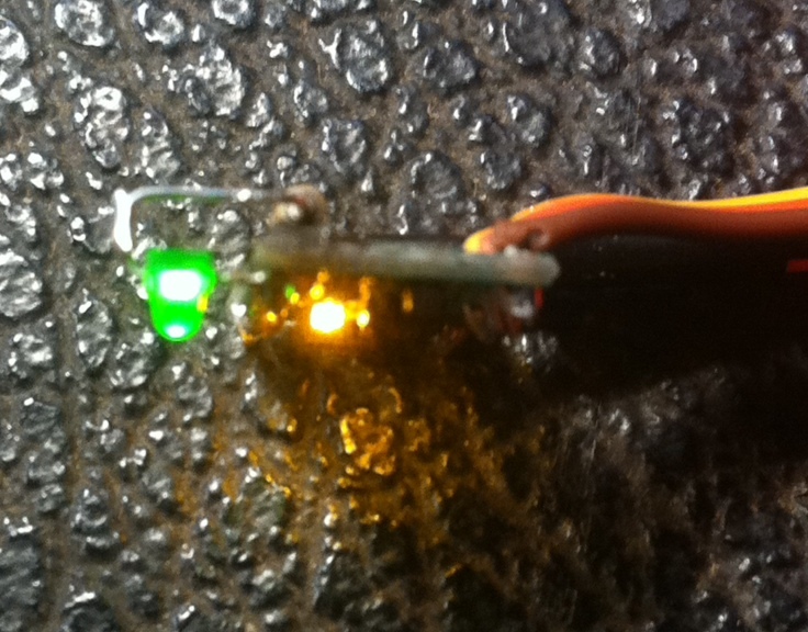
I wired in a 180 watt, 1/8w resistor to the 2.1 forward voltage, LED to give me 18ma. This is just a indicator light so I didn’t need to push the max for brightness. It works perfect. I used a little black silicone on some of the traces so as not to short anything when I wired in the resistor. This Pololu RC switch is then piggybacked onto a high current LED driver. The yellow, built in LED flashes differently when the switch is in the “ON” position, but I wanted to add something a little more obvious.
Sorry for the blurry photos, this is the best my iPhone can do this zoomed in. You get the point though.
How to add an “ON” indicator LED to the Pololu RC switch.

Hiya! Looks sweet.
Quick comment, you said 18mA
I think there’s a small error there,
I get ~16mA
5V - 2.1V voltage drop = 2.9V
2.9V / 180 Ohms = 16.1mA.
(I’m picky here :P)
Lol, you got me! I used an online calculator. I think it rounds off. I used 5% resistors.
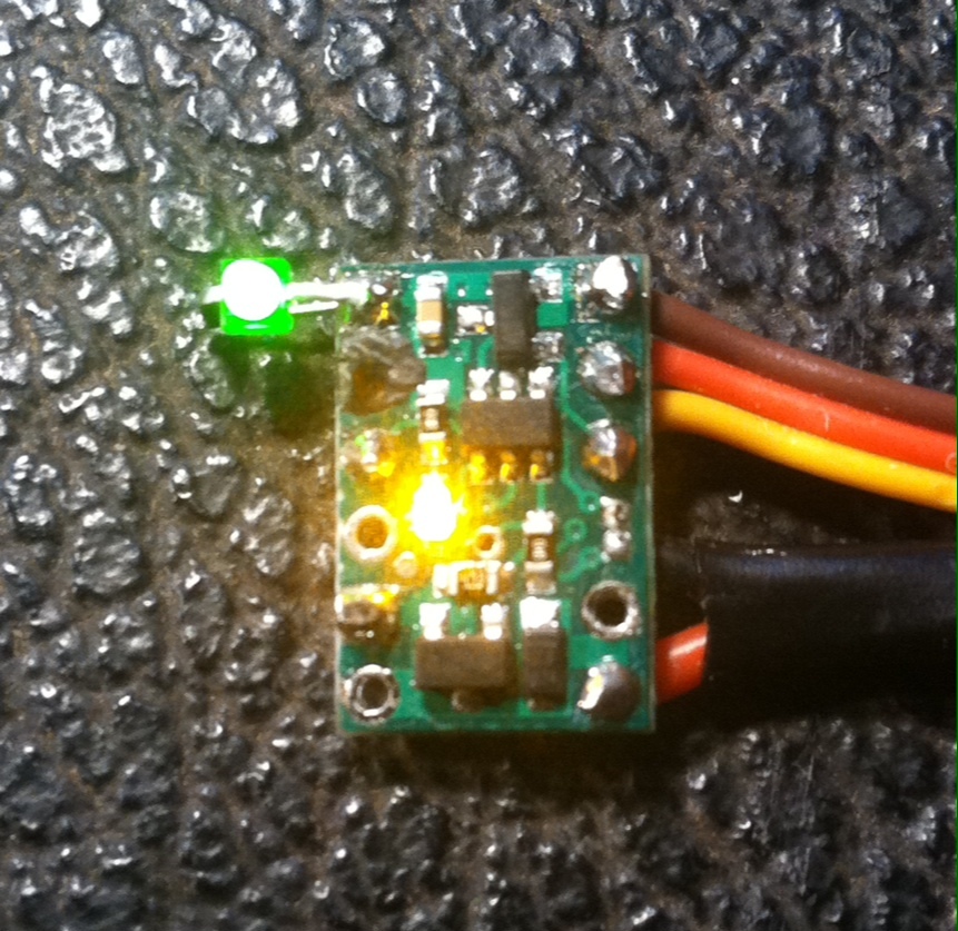
I’ll try and get better pics.
The green LED is 2mm for reference.
Smart calculator! It rounds for “worst case scenario.”
My guess is this: 2.1 V is your forward drop “+/- 0.1V”
So worse case is 2.0V and 180*0.95 = 171 ohms
3 V / (180 * 0.95) = 17.54mA = 18mA rounded!
