I am using the 24v23 CS driver and am able to make it work fine in drive-brake mode, typically using a PWM frequency of about 18 KHz. However, when I tie PWML and PWMH together for drive-coast mode, it only works with very low PWM frequencies, below 100 Hz. For example, with a 50% duty cycle, the value of OUTB - OUTA (direction L) starts at 50% of V+, but, as the PWM frequency rises above about 100 Hz, the value of OUTB - OUTA rises to about 80% of V+. At 18 KHz, the duty cycle doesn’t matter, the value is fixed near V+.
The scope traces show OUTA in yellow and OUTB in blue. The input PWM signal is not shown, but was verified to be a sharp square wave with the correct frequency and duty cycle.
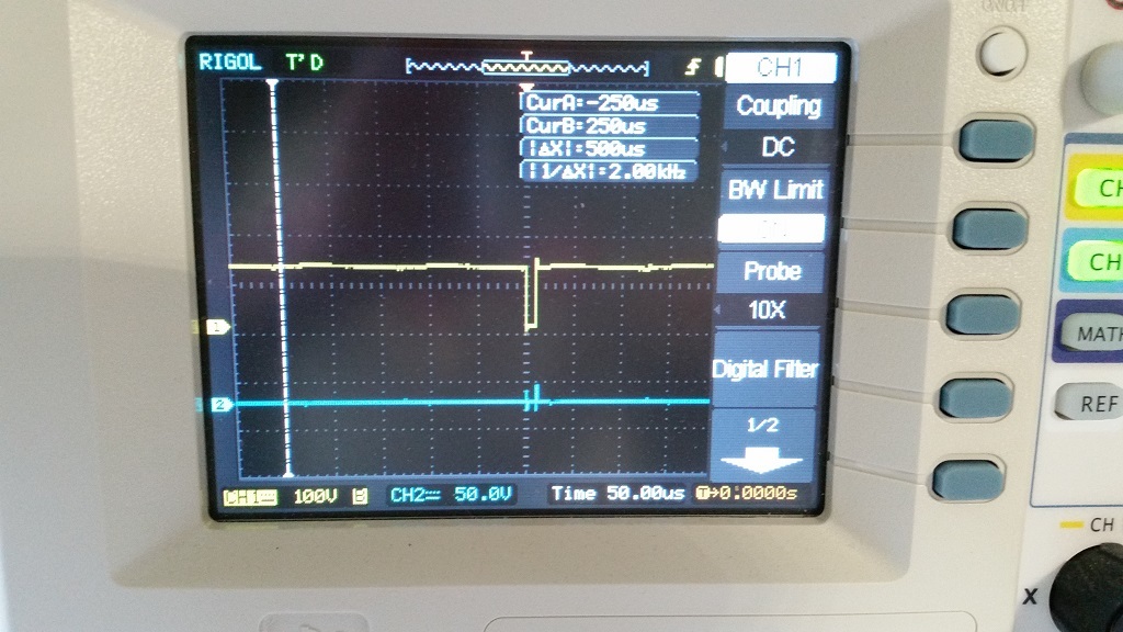
move-coast: OUTA and OUTB with a 50% duty cycle and 8 KHz PWM, as you can see, it only has a small pulse.
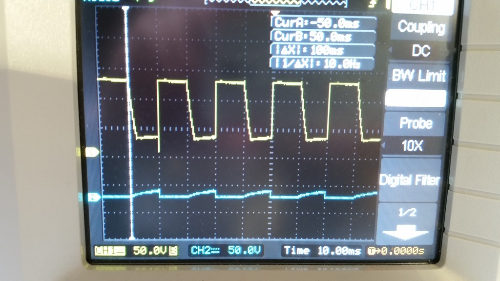
move-coast (PWMH and PWML tied together, getting PWM signal): OUTA and OUTB with a 50% duty cycle and 50 Hz PWM. You can see that there is what appears to be capacitive decay on OUTA and rise on OUTB. As the PWM frequency increases, that decay takes up more and more of the PWM cycle.
move-brake (PWMH getting PWM signal and PWML held high): working fine with just an 8 KHz PWM signal
I was able to upload the attachments after a forum bug was fixed (see replies below).
I am sorry you are having problems using your high-power motor driver. It would be nice to see those oscilloscope captures. It looks like there was an issue with our forum not allowing for files to be uploaded. We have since fixed the issue. Could you try uploading those captures again? If you continue to have problems uploading the pictures, you could try uploading them on image-hosting sites like Photobucket or ImageShack and use the “IMG” tags to post them.
Those captures look like what I would expect. There is less time for the voltage to decay during drive-coast mode at the higher frequencies than at lower frequencies. With a larger load, you might see the voltage drop quicker. Did you have any kind of load on your motor when you took these captures? Are you able to ramp up the speed in drive-coast mode?
Those images and measurements were under no-load, as I was setting up the drivers.
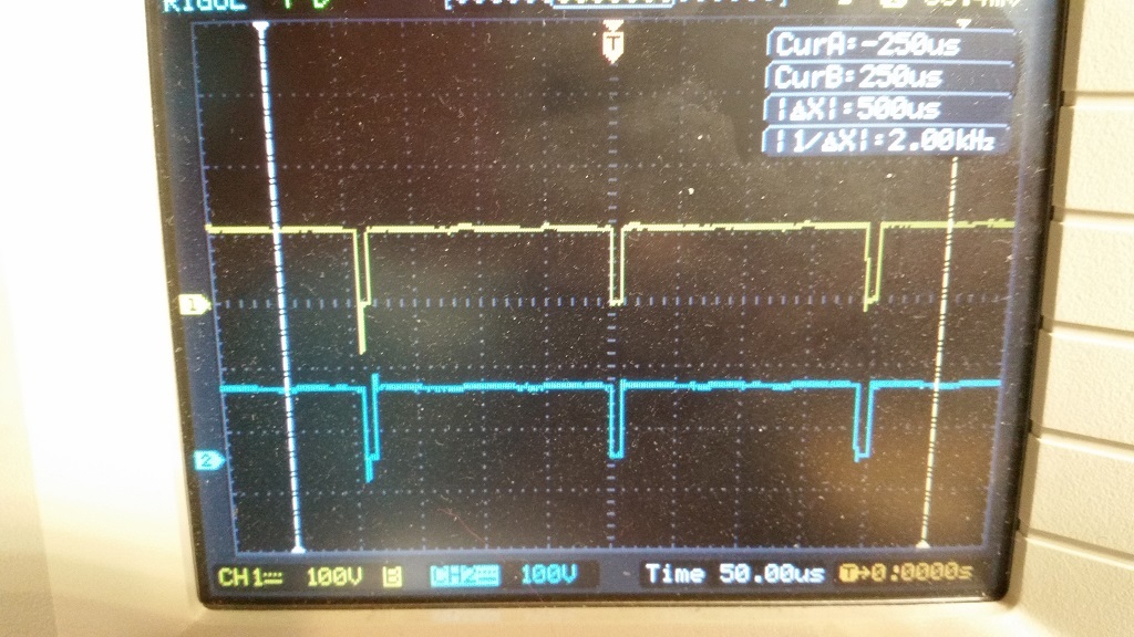
Under load the waveforms look better, but the basic problem remains. See the images for 12%, 25%, and 50% duty cycles. The waveform does not change when going from 25% to 50% duty cycle
What kind of load did you connect? Could you connect one of your oscilloscope probes to the PWM input and take new screen captures? Could you also post pictures of your setup?
The load was a 12V 100W brushed DC motor with moderate resistance.
I did examine the input PWM and it is fine-- see the original sets of slides and you can see the clean output in move-brake mode indicating a good PWM input.
Overall, I’m not interested in spending more time diagnosing this, as I am going to use move-brake mode anyway and the circuitry is now all in place, so it is hard to get o’scope probes in the path.