Hi,
Apologies if this question has been asked before, but I searched the forum and couldn’t find this issue. My buddies and I are putting together a differential drive robot, and using an Arduino (Mega) and a pair of Pololu micro metal gear motors (75:1). We’ve got the bot up and running, but we’re struggling with the encoders. Basically, when we send the robot in a straight line, there is a significant discrepancy between the encoder readings. One (the same one) always reads like it’s going 25-30% faster than the other, even though the robot moves in a straight line as we intended. The wheels and tires (Pololu) are identical. We’ve got both encoders tied to interrupts on the Mega, and we’re simply doing counts++ every time the interrupt is triggered on a change. We’ve tried running at different speeds, and the distance actually covered by the robot matches the counts on one of the two encoders, so I don’t think we’re missing counts. We have also tried switching which motor goes to which pins on the Mega, and even swapped the order of interrupt functions in the code, but we see consistent results: the same physical encoder, however it is wired up, reads 25% high or more.
Has anyone ever seen something like this before? Thanks in advance for any help.
Hello.
That is strange. Can you tell me more about your setup? Which encoder board are you using? If you are using our optical encoder board, are you using the 3-tooth or the 5-tooth wheel?
Can you remove the load from both motors (e.g. you might be able to just flip the robot upside down) and try running the motors at the lowest speed that gets them moving, and see if you get the same behavior?
Do you have access to oscilloscope? The encoder outputs might need some additional conditioning, and an oscilloscope would help a lot in figuring out what is going on.
-Jon
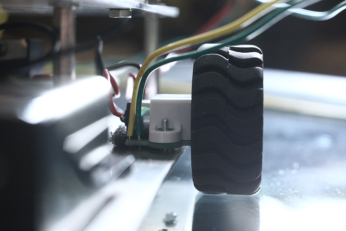
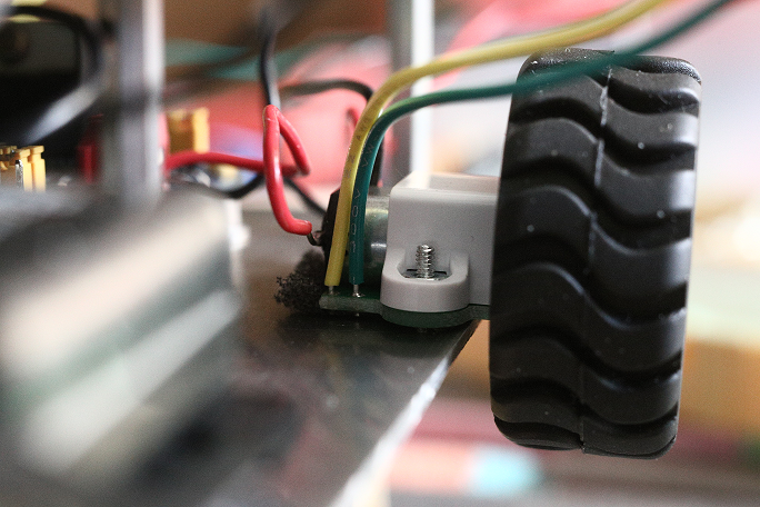
Thanks very much Jon. We are using the 42x19mm wheels with the matching quad encoder (item 1217), matched up like so: https://www.pololu.com/picture/view/0J1203
We have tried running the robot with at slow speed under no load, and we get the same result. We do have an O-scope though and haven’t tried that - we’ll do that next.
The mystery continues… My friend and I used a 16-ch digital reader instead of the O-scope and got the results below. The first two channels are the encoders on the left motor - this is the one that is having the problem. The other two channels are the right motor encoder, which is working properly. I was incorrect in my original post - the faster motor is reading correctly, and the slower one seems to be missing counts. The last two channels are the left and right PWM signals.
So clearly the first channel on the left motor is the problem. It seems to read high and miss a whole bunch of counts at a periodic cycle. The period? It is approximately equal to once per wheel rotation. It’s as if we painted half of the teeth on the inside of the wheel black, only we didn’t.
Do you think this is a problem with the optical sensor for that channel, or the wheel? Have you ever seen something like this before?
Thanks again for the help.
Hi guys,
This is Brian, SpikeyD’s friend working on the same project.
If I have the time tonight I’m thinking it may be helpful to try spinning the wheels in reverse and then also seeing if the problem persists when oscillating between forward/reverse. It seems like there must be a physical problem to see missed counts like this, as opposed to a software/electrical issue.
We are using the wheel encoder assembly a little differently than intended, as well. We have put a small amount of nonconductive foam under the assembly to make a poor man’s suspension; this eliminated some ‘wheel hop’/‘slipping’ we had run into initially. When unloaded, the wheels have a positive camber, but once we lay it on the ground it zeros out and works quite nicely. Seems like maybe this would be the root cause of the missed counts, as if sometimes the infrareds miss the teeth, but the one wheel misses no counts and is mounted identically… so I’m skeptical now that this suspension setup is the problem.
Can you try turning the trimmer potentiometer closest to the sensor that is not working properly in a clockwise direction? Please be careful when doing so, the trimmer potentiometer is very small, and it can be damaged by using a screwdriver that is too big for it.
By the way, you mentioned that the foam you are using is non-conductive, but is your chassis conductive? If it is metal or some other conductive material, and the foam you are using does not fully cover the underside of the encoder board, it could short together parts of the board and potentially damage it.
-Jon
We can certainly try adjusting the trimmer. What does that do? (Im sure its explained somewhere, Im just being lazy).
And yes, we should probably put some electrical tape down on the chassis there under the foam or something. Originally we had washers standing off the PCB, but we got anxious installing the foam – didnt think about the chassis. Thanks for the tip.
The potentiometer basically shifts the voltage level of the raw signal going from the phototransistor circuit to the Schmitt trigger. You can look at the schematic on the product page to learn more.
If that does not help, it might be that the encoder board is slipping away from the wheel’s teeth due to the vibration of the gearmotor, which is now not as well damped since it is resting on foam instead of the rigid surface of your chassis. To test this, you could trying removing and replacing the wheel on the same micro metal gearmotor shaft to reposition the teeth on the wheel relative to the encoder board. You might also try swapping the wheels.
By the way, removing the wheel can be difficult. If you decide to try this, you might find it useful to use a screwdriver to push axially down the center of the motor shaft while pulling the wheel towards you with your fingertips.
-Jon

