Arduino Nano V3 resetting (DRV8835)

Hi guys (and girls),

The Background

I have a small robotic company and I sell kits to students and newbie hobbyists. The kits consist off a small mobile robot bundled with a couple of sensors, two micrometal DC motors, an acrylic structure plus some other parts, most comes from Pololu. Everything is controlled by a regular Arduino and an Adafruit Motor Shield (v1) powered with 4xAA NiMH batteries.

This kit is very popular, but we are not satisfied with the overall performance, mainly because the restrictions imposed by motor driver shield we are using. It is a very good product but we don’t like:

  • Having 4 DC motor connections when we only really need 2;
  • Loosing almost all digital Pins to control the H-Bridge;
  • Bad performance when controlling 3V micrometal gearmotors;
  • Consumes too much “real estate” space in the chassi structure;

Our first attempt to improve the kit overall performance was to increase the input voltage going to 6xAAA batteries (7.2V~9V) and changing the 3V motor to 6V versions. Unfortunatelly (don’t know why) it didn’t improve well.

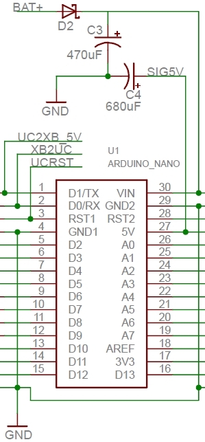
So we decide to take a more ambitious step and design “our own” shield. The idea is to take an Arduino Nano V3, a DRV8835 motor driver and create an “undershield” to make all necessary connections consuming the smallest space as possible.

The guidelines we have are:

  • Share the same power source to control the Arduino Nano v3 and drive the motors; [EXTREMELLY DESIRABLE]
  • Connect the control pins between the Arduino Nano v3 and the motor driver;
  • Breakout all digital and analog pins with 5v and Gnd connections;
  • Keep a small board size;
  • Work realiably

What we have developed

I’m not an Electronic Engineer, my background is computer science, but the goal seems simple to achieve.
I opened eagle, designed a schematic, created some components and routed the circuit. Before sending the design to OSHPark, I took a protoboard to test it out.

It didn’t work. :frowning:

When I connected only one motor it seems to work fine, but when I connected the second one the Arduino keeps resetting. When the code runs, the motor give me some “HUM” and then the Arduino resets. After some research I figured it out: The DC motors were introducing noise in the circuit and I needed some decoupling capacitors.

So I did it:

  • Placed .1uF ceramic caps between the motors terminals;
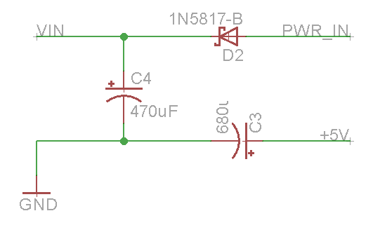
  • Placed a 200uF electrolytic cap between the VIN and Ground, close to the Arduino connection;
  • Twisted the motor cables and the power source cable (6xAAA back-to-back battery holder);

It got better, but no success. :frowning: :frowning:
The Arduino could start the motor and keep them running, but every time I change the motor direction it resets. :frowning:

The current (not in amps) problem

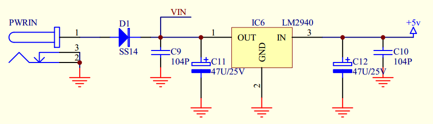
After further research, I discovered that changing the Electolytic cap to 470uF and placing it between the 5V and Gnd (instead of VIN) of the Arduino, solved the problems. I was happy. But then I made some stress tests. Created a code to change both motor directions at the same time at intervals of 200ms. After a few seconds the Arduino resets. It also resets pretty fast if I stall any of the motors.

I know that having two separate power supplies (with common ground) is probably the easiest answer, but as a design goal I want to have a single power supply for the whole system. That’s the way the Adafruit Motor Shield (schematic) always worked, I also used the DFRobot Romeo board (schematic) the same way. But they are based on the L298 and L293 H-Bridges, I’m not sure that’s the difference.

I’m seeking help here to find out a way (change the schematic) to solve this issue.

Stress code:

int D1 = 4;
int V1 = 5;
int D2 = 7;
int V2 = 6;

void setup() { 
  pinMode(D1, OUTPUT);
  pinMode(D2, OUTPUT);
  pinMode(V1, OUTPUT);
  pinMode(V2, OUTPUT);
}

void loop() {
  digitalWrite(D1, HIGH);
  analogWrite(V1, 255);
  digitalWrite(D2, LOW);
  analogWrite(V2, 255);
  delay(200);
  
  digitalWrite(D1, LOW);
  analogWrite(V1, 255);
  digitalWrite(D2, HIGH);
  analogWrite(V2, 255);
  delay(200);
}

any input is really welcome.
Thank you all !!

Hi.

Thanks for sharing so much detail about your project. Since it is resetting when you add another motor or switch the motors from full speed forward to full speed reverse, it sounds like it is a power issue. I suspect that when you do those things the motors draw a large amount of current from the batteries and cause the voltage to drop. If the voltage drops low enough, the Arduino or driver resets. If you have an oscilloscope, you could use it to monitor those voltages and see any drops.

Adding the capacitors probably helped because they did not allow the supply voltages to drop as quickly. I recommend adding more capacitors to your supply lines or playing around with different capacitance values on VIN and 5V to see what helps. If that doesn’t seem to work, you could also try a supply that is capable of outputting more instantaneous current like a LiPo battery or desktop supply. You might also consider implementing some kind of acceleration limiting in your program to prevent the motors from drawing large currents.

You mentioned that you are using “micrometal gearmotors”. Are they from us? If not, do you know their stall current?

-Claire

Hi Claire,
thank you for your input.

The motors I use are not sourced from Pololu, but they are the same dimensions, and (I believe) perform similarly. Unfortunately I don’t have an oscilloscope nor a bench supply to debug the problem. I remenber doing basic measurements in the past, the 3V/100RPM version goes around 40mA free run to 300mA stall.

I have 10 units of this 6V/300RPM I’m working on and I will make some new measurements with my crappy multimeter to post the results. I will use new and fully charged NiMH to reduce the risk of batteries being a source of problems.

During my research I read something about the motors dropping the voltage and I agree with you that’s the possible reset cause (I will try to measure this drop too).

The curious thing is that with the same motors I never had problems with the “Arduino UNO + Adafruit Motor Shield” combo neither with the DFRobot Romeo board.

My curiosity led me to dive in the schematics of those products and maybe there’s the answer.
Comparing the Arduino Uno and the Romeo Board schematics with the Arduino Nano schematics, both uses a low dropout voltage regulators (NCP1117 and LM2940 respectively) coupled with some caps. That doesn’t happen with the Nano, the voltage regulation is very simplified, no caps at all, and a uA78M05 regulator.

Following are the details of each regulators:


My guess is if I try to recreate the Uno/Romeo regulation and supply the Nano 5V directly, maybe I’ll solve the issue. But as long I’m no EE I can’t say that’s the way to go.

-Guilherme

It does seem like the differences in the regulator circuits of the boards you previously used (the Uno and Romeo) and the Nano are probably adding to the reset issue you are having. One big difference is that the NCP1117 and LM2940 regulators both have a dropout voltage of around 1V, where the uA78M05 has a typical dropout of 2V. That means that the supply voltage for the Nano has to be above about 7V for it to work properly.

Like you pointed out, the regulator circuit on the Nano not having any built in capacitors might also be causing problems. There is no recommended schematic given in that regulator’s datasheet, but from the footnotes given about how the regulator was characterized, it seems like at least one capacitor on the output and input should probably be used.

Supplying 5V directly to the 5V line of the Nano might make things better, and I don’t see any obvious problem with trying it.

-Claire

Hi Claire,
thanks for the input.

As promised, I took the measurements of the motors and the average free-run current is 40mA and the max stall current is 650mA (520mA average). That seems fine at the driver specification.

Now, back to the circuit.

I forgot to measure the voltage drop at the VIN line.

Anyway, I think that a better solution than bypass the Nano regulation building my own voltage regulation circuit is to split the power line and protect the microcontroller VIN with a shottky diode. This way, when the motors draw a lot of current and the voltage drops, the diode will prevent the charge stored in the caps to flow back to the motors. This will probably give the micro much more time to wait for the situation to come back to normal.


I didn’t came up with this idea alone, I found the solution in this Arduino Nano Carrier board from MIT.


I don’t have any diode available now to test it out, but as soon I get one I’ll post an update here.

The other possible idea is to try using the Arduino Micro (or maybe Pololu’s A-Star), instead of the Nano. :slight_smile:

-Guilherme

Using the Arduino Micro or an A* micro would probably help, but the Schottky diode solution might work too. If you do try out that circuit, I would be interested to know how it works.

-Claire

Hi Claire,
just to give a late follow-up:

The diode placement worked flawlessly, the Arduino held the stress well even with just a smaller cap (100uF) in the 5V line.
I sent the boards to OSHPark for prototyping, but don’t have them yet.

thank you for all your help.