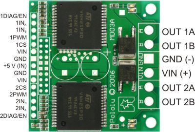
I should control 12v wipermotors with Dual VNH3SP30 Motor Driver with arduino. I’m a quite newbie when it comes to electronics. Could some one tell me what pins of the VNH3SP30 should I connect to get control to the motors. The motor pins and supply pins at the right side are quite clear but which pins of the left side should be connected to arduino. I’m confused coz there’s more pins than assumed there to be. For example there is plenty of those 5v pins? So which are required to drive motors at the desired speed and direction.
Have you looked at the datasheet? Page 7 shows a truth table and typical application. INA and INB set direction, PWM is for PWM (outputs according to INA and INB when high, outputs disabled when low), CS is the current sense output, and DIAG is the error output.
I don’t know what you’re talking about regarding “plenty of those 5v pins”. I see one. There are a couple of extra VIN pins on the left side; those are just for your convenience since the main supply (VIN) often will be your microcontroller supply.
I didn’t notice the datasheet under that tab. Now I found it. Thanks.
I get the PWM pulse signal from arduino. So I input that to PWM and i need other two digital signals to choose the direction. Then I also need +5v to en/diag -pins and a supply +5V. Right. Then I connect my motors and kick in the (for example) +12V main supply voltage. Then I got my pololu and motors up and running. Did I get this correct?
When I said “plenty of those 5v pins” I ment those vin -pins. I didn’t quite understand what is the purpose of those. Is it enough if I input a logic supply 5v to + 5V (in) -pin and leave the rest vin-pins unconnected?
Is it safe to connect arduino directly to pololu or is some safe circuits or components needed?
Sorry about my rudimentary questions. I will learn and wont be asking so stupid questions in the future.
You can connect directly from the Arduino to the motor driver. You do not need to connect anything to the extra VIN pins on the left side. You don’t need to connect 5V to the en/diag pins; you can treat them as outputs that you can initially ignore (though you might want to look at them if you have any problems).
I still got some question marks:
Jan, you said:
-“You don’t need to connect 5V to the en/diag pins; you can treat them as outputs that you can initially ignore”
However, the data sheet tells me:
-“In normal operating conditions the DIAGX/ENX pin is considered as an input pin by the device. This pin must be externally
pulled high.”
…and…
“Open drain bidirectional logic pins. These pins must be connected to an external pull up resistor.When
externally pulled low, they disable half-bridge A or B.”
So I find these statements a bit contradictory. Jan, you say that I can ignore them while the datasheet tells me (as I understand it) that they must be pulled high externally. I don’t doubt your words Jan. I’m just wondering what didn’t I understand correctly.
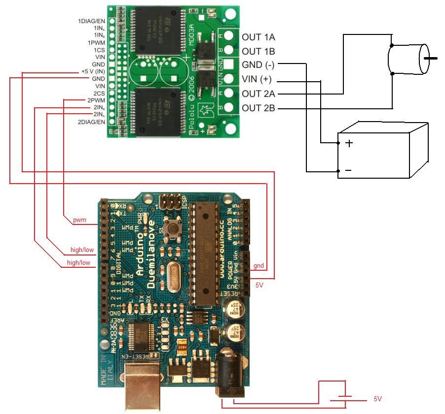
In the enclosed picture I’ve scetched how I would now connect pololu driver with arduino corresponding to that i’ve learned here. Thanks Jan!
There is no contradiction in what Jan and the datasheet says. Take a look at the schematic drawing at the bottom of the product page for the Dual VNH3SP30 Motor Driver Carrier MD03A; there is a pull-up resistor between en/diag pins and VCC.
I got my arduino-pololu -motorcontrol set-up up and running thanks to your guidance.
My project was halted for a quite a while. Now I did the set up excactly like before (except I have a different power supply) but now my motors wont turn. I dont get any life on the motor driver. I believe the problem is on the VNH3SP30 (or the connections).
So my questions are:
Could you give me some hints where to start digging the fault? I guess there are quite common things that could happen and ruin the board. E.g. is there some pins I could measure or monitor to see if my pololu VNH3SP30 is burnt or something equivalent.
I dont get those leds on the board powered. Should those leds be lit when driving “motor” even if I wouldn’t connect any motor?
Can I imput steady 5v signal to pwm pin to simulate 100% duty signal in order to test with more simple set up (I dont have oscilloscope to study the signals moro thoroughly). What would be the very simplest setup which I could use to test if my motor driver is still alive.
I highly appreciate ur help. Please let me know if I could provide some further data to help you to hint and support me.
Is there any reason (e.g. burnt electronics smell, a time you zapped it with static, etc.) to think the board is damaged? If the only thing you changed is the power supply, I’d start with checking that. If you took everything apart and reassembled it (or even if it was built on a breadboard and jostled around a lot), it could be that you don’t have everything wired correctly. You can put 5V on the PWM line. The LEDs should turn on even without a motor present. The simplest test would be to connect power supplies and then make PWM high while making one of the direction inputs high and the other low.
When you build up some static electricity on yourself and then touch something metal, you can get a big zap (spark). If you do that to your electronics, you might damage it.
I was trying with the same hardware (arduino, same driver, same motor).
I did the wiring as in the sketch above (but for a small amount of time where the polarity for the motor side on the driver board has been inverted [I checked it with a multimeter]).
I connected just one motor, just to try.
The motor did some spins then both the capacitors exploded.
The capacitors are polarized and are before the reverse power protection circuitry, so your connecting power backwards is almost certainly the reason they exploded. The rest of the board should be fine, but you will need to replace the caps.
Hi,
I’m warming up an old project of mine. My previous problems were related to bad connections. After soldering everything properly together, the pololu driver started to work again.
Now I’m facing another issue. If I load mechanically the motor I’m running with the pololu driver, the driver “dies”. If I shut down the power and power it up again the motor starts to run again. So what is causing this “dying”? And how can it be worked around. I understand I can’t load the motors really heavily and have them running, but could I get them back running after stall without shutting down and up the power.
So what is actually happening here.
I’m running basic 12v wiper motors with the driver and powering it with ATX supply.
It sounds like you are potentially overheating the driver or drawing too much current from your power supply. What is the stall current of your motor and what are the specs of your power supply?
These are things you really need to know in advance so you can choose the appropriate motor driver and power source for your motor. Stall current is the current the motor draws while it is stalled, and it will vary linearly with motor voltage (so you can always measure it at a lower voltage and calculate what it would be at your operating voltage). As your motor load increases, the current draw will approach the stall current. When your motor first starts from rest, it can briefly draw the full stall current, and if you ever change directly from full speed forward to full speed reverse, it can briefly draw nearly twice the stall current. Can you at least tell me the voltage of your power supply?
Note that the VNH3 has several latching fault conditions (see the datasheet for more info), one of which is overtemperature. When such a fault condition occurs, the outputs turn off and remain off until the condition ceases and the affected input pin is toggled (or until, as you’ve already discovered, the board is power-cycled.
I take 12v from ATX supply. I need to dig out the amp ratings.
The motor is typical 12v car wipermotor. I’ll measure the stall current according your tips (with low voltage).
I added in the controller logic an inversed direction setting before writing the actual direction to the INa and INb. This keeps the motor spinning but is not the right solution. It’ll kill the driver eventually, I guess.
I write (pseudo code):
if forward:
INa = False
INb = True
INa = True
INb = False
else if backward:
INa = True
INb = False
INa = False
INb = True
endif
I noticed, the driver will wake up if I change the direction after stall. So instead of power-cycling the driver I write the direction in every loop like I described before.
Let’s assume I wanna drive the motor forward and in order to get forward direction I need to set:
INa = FALSE
INb = TRUE
But to ensure the dir pins get latched up and down I write inversed values first.
INa = TRUE;
INb = FALSE;
INa = FALSE; // <= actual dir set
INb = TRUE; // <= actual dir set